Weller WMA-1 rework station not working

Thread Starter

Midsomerdave

Joined May 23, 2014
28
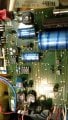
Hi, This is a Weller WMA-1 rework station. Switched it on as usual but noticed smoke. When opened the resistor ringed in the pics was still smoking slightly. Also, the 200mA fuse to the resistor was blown. I can't see any other burns/damage on the board....underneath looks fine. In laymans terms, can anyone suggest where I should look for the real 010.jpg 010.jpg 014.jpg problem? I cannot get hold of a circuit diagram anywhere. Many thanks if you read this. Dave.
 

Attachments

MrChips

Joined Oct 2, 2009
30,821
Sorry, but the title of your thread should read something like:

Weller WMA-1 rework station not working

That would be much more helpful to readers.
 

Aleph(0)

Joined Mar 14, 2015
597
@Midsomerdave sry that this isn't vry original:oops: 
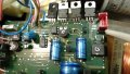
But 1'st troubleshooting step is checking electrolytic caps. They're always prime suspect in cases of over current issues! Then if they're not problem a schematic would be vry nice:)!
 

Aleph(0)

Joined Mar 14, 2015
597
Nope, replaced a couple of caps and a voltage regulator on the same line and it smoked another resistor! Aaarrgh!
Midsomerdave o/c finding schematic is easiest means to solution. If that's not option you could do some reverse engineering of circuitry _electrically downstream_ of overheating resistor (which I know can get vry tedious:(!).

So w/o schematic my suggestion for next step is to _shotgun_ likely suspects by checking power-semiconductor{s} (prolly thyristor{s} or mosfet{s}) that switch/regulate power to heating element. So if that seems counter-intuitive all I can say is that damage in low-power driver/control stages is often result of shorted final power output stage (which has relatively high failure rate). So plz keep us posted to your progress:cool:!
 
Last edited:

Dodgydave

Joined Jun 22, 2012
11,304
Weller use Triacs to pulse the heaters with a thermocouple sensor, here is a Weller pu-81 model, don't know if will help...


weller pu-81.png
 
Last edited:

LesJones

Joined Jan 8, 2017
4,190
Here is the schematic of the Weller WSP80 soldering iron controller.

Weller_WSP80_PSU.jpg
This iron uses a thermistor of some sort rather than a thermocouple. Here are some measuments of the resistance at a few tenperatures.
Temperature sensor.
Resistance.
Room temp (20 C) 22.5 ohms

250 C 37.5 ohm
300 C 40.4 ohm
330 C 42.3 ohm

The method of operation looks very similar to the schematic of the PU-81 that DD posted in post #9 although it is implemented with different components. This is a link to the datasheet for the T2117 zero crossing IC used in the PU-81

Les.
 

Aleph(0)

Joined Mar 14, 2015
597
Here is the schematic of the Weller WSP80 soldering iron controller.

So since R16, R23 and R26 are only resistors with significant figures of value ="4" and "7" (from pics on OP, burned resistor marking is Yellow, Violet, multiplier unreadable) and since, based on values and positions in circuit, it's basically impossible for R16 and R26 to have over current failure, damaged resistor has to be R23! So I say base junction of Q3 is suspect. So for example if _rectified AC_ (on schematic) means FW rectified AC from line, then power dissipation of R23 could be as much as ≈ 3Wrms or 12Wrms (depending on line voltage) and if rectified line voltage is also filtered it could be as much as 6Wdc or 24Wdc so in all cases 1/8th watt resistor would be insty toast:eek:!

So @Midsomerdave plz check base junction of Q3:)

PS so looking further on schematic, since output of Q3 is clock input to flip-flop, AC definitely isn't filtered. But that doesn't change fact that shorted base junction would definitely kill R23 depending on voltage of _rectified AC_:cool:
 
Last edited:

LesJones

Joined Jan 8, 2017
4,190
We have to bear in mind that the Weller WMA-1 is a rework station and the two schematics are just soldering irons. They might just give an idea about how Weller design things. I think the TS will have to trace out at least part of the schematic.

Les.
 
Top