Weller WES51 not working

Thread Starter

Ams Sma

Joined Feb 11, 2017
17
Hello

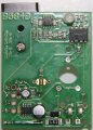
My Weller WES51 suddenly failed.
The led doesn't turn on and the tip is not heating

I've checked the power switch the transformer and the voltage of the microcontroller(PIC 12CE673). Everything seems to be ok.

When i tried to check the controller clock and touched with the negative terminal of the oscilloscope in the gnd of the chip the station started to work.
When i remove the negative terminal of the oscilloscope from the gnd of the pin the station stops immediately.

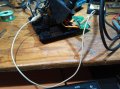
I know that the negative terminal of the oscilloscope is connected to the earth.

The tip of the weller has continuity to the earth terminal.


Any ideas where is the problem?

Tnx!
 

Attachments

ebp

Joined Feb 8, 2018
2,332
It is hard to tell for sure from the photo, but the insulating sleeve on the capacitor just above the 8-pin SO package in the lower right corner looks to me like it has "slipped". Usually more of the sleeve wraps around the top of the cap. Slipping sometimes happens when caps have overheated due to "wearout."

-unless that is an inductor and just looks like a capacitor! (but inductors don't usually have that 5-sided base)
 

Thread Starter

Ams Sma

Joined Feb 11, 2017
17
It is hard to tell for sure from the photo, but the insulating sleeve on the capacitor just above the 8-pin SO package in the lower right corner looks to me like it has "slipped". Usually more of the sleeve wraps around the top of the cap. Slipping sometimes happens when caps have overheated due to "wearout."

-unless that is an inductor and just looks like a capacitor! (but inductors don't usually have that 5-sided base)
Thank you for the reply

I think its a circuit breaker
I think Its more visible in the next picture
 

Attachments

ebp

Joined Feb 8, 2018
2,332
I was referring to the part marked
4G
33
35J
It is a capacitor, but it looks OK. It was just shadows and reflections that made me suspicious.

The thing in the glass tube is a bit mysterious. It looks like a magnetic reed switch. I believe some versions of that iron have a setting lockout - if you remove something from the control panel the temperature setpoint can't be changed. A reed switch operated by a magnet would be suitable for such a task.

Have you looked on the web for a schematic?
 

Thread Starter

Ams Sma

Joined Feb 11, 2017
17
The component in the lower left corner of the second picture looks like a fuse. If it is, is it opened?
Hello

The component seems to be a kind of fuse or circuit breaker and its not opened. The station doesn't work even if bypass it.

If i connect the earth terminal in any part of the ground in the circuit the station works.
 

Thread Starter

Ams Sma

Joined Feb 11, 2017
17
I was referring to the part marked
4G
33
35J
It is a capacitor, but it looks OK. It was just shadows and reflections that made me suspicious.

The thing in the glass tube is a bit mysterious. It looks like a magnetic reed switch. I believe some versions of that iron have a setting lockout - if you remove something from the control panel the temperature setpoint can't be changed. A reed switch operated by a magnet would be suitable for such a task.

Have you looked on the web for a schematic?
Thanks for the information about the glass tube.
I've tried to find a schematic but couldn't find one.
I only find a manual with some test procedures but no schematics.
 

Reloadron

Joined Jan 15, 2015
7,501
The component in the lower left corner of the second picture looks like a fuse. If it is, is it opened?
Just as a side note the WES 51 has a small ESD symbol on the front of the case. When the board is installed that glass tube looking thing sits right behind the front panel ESD symbol. I believe it is a magnetic reed switch. The WES 51 has a temperature lockout feature:
"ACTIVATION OF LOCKOUT FEATURE 1. Adjust the temperature set knob to the desired tip temperature. 2. Apply the Lockout Pencil to the ESD symbol on the front panel until the LED starts slowly (5 Hz) blinking Red. Remove the Lockout Pencil within 2.5 seconds and the temperature setting will be Locked in. The indicator LED will be Red and turning the temperature set knob will have no effect on the tip temperature. 3. Reverse the lockout by applying the Lockout Pencil to the ESD symbol until the LED is slowly blinking Red. Remove the Lockout Pencil within 2.5 seconds and the temperature set knob will function normally and the indicator LED will be Green. Note: If the Temperature Set Knob has been adjusted during the Locked Mode, the station will control to the new set point, once the Lockout feature has been disabled".

I see that was covered and here is the owners manual.

Since applying scope ground makes it come alive and work I would start at the line cord and follow ground through the board. Seems like an open ground or common somewhere.

Ron
 

Thread Starter

Ams Sma

Joined Feb 11, 2017
17
Just as a side note the WES 51 has a small ESD symbol on the front of the case. When the board is installed that glass tube looking thing sits right behind the front panel ESD symbol. I believe it is a magnetic reed switch. The WES 51 has a temperature lockout feature:
"ACTIVATION OF LOCKOUT FEATURE 1. Adjust the temperature set knob to the desired tip temperature. 2. Apply the Lockout Pencil to the ESD symbol on the front panel until the LED starts slowly (5 Hz) blinking Red. Remove the Lockout Pencil within 2.5 seconds and the temperature setting will be Locked in. The indicator LED will be Red and turning the temperature set knob will have no effect on the tip temperature. 3. Reverse the lockout by applying the Lockout Pencil to the ESD symbol until the LED is slowly blinking Red. Remove the Lockout Pencil within 2.5 seconds and the temperature set knob will function normally and the indicator LED will be Green. Note: If the Temperature Set Knob has been adjusted during the Locked Mode, the station will control to the new set point, once the Lockout feature has been disabled".

I see that was covered and here is the owners manual.

Since applying scope ground makes it come alive and work I would start at the line cord and follow ground through the board. Seems like an open ground or common somewhere.

Hello
Thanks for the manual.
I'm measuring a resistance of 500k between the secondary of the transformer and the ground .
If i connect one of the secondary terminals to the transformer core (which is connected to ground)the station works.
 

Attachments

Reloadron

Joined Jan 15, 2015
7,501
It's a little peculiar. They come in with mains power and mains ground is tied to the transformer core and also runs out grounding the tip. Mains neutral uses what looks to be a wire nut and ties to one side of the transformer primary while mains hot is switched and goes to the other side of transformer primary. The transformer secondary looks to be the red and yellow leads which go to the board. With your jumper removed you may want to look for AC voltage on the red and yellow transformer secondary which you should be able to switch On/Off using the power switch. Matter of fact I would make sure your mains power is there and switched on the transformer primary side. If you have AC going in to the board on the Red & Yellow that has to be somehow rectified to power the board? I just don't know where or how? Thinking more about it I can't see where ground is required or why when you apply ground the thing works?

Ron
 

thedoc8

Joined Nov 28, 2012
162
Hello

The component seems to be a kind of fuse or circuit breaker and its not opened. The station doesn't work even if bypass it.

If i connect the earth terminal in any part of the ground in the circuit the station works.
Maybe just a bad cord
 

Thread Starter

Ams Sma

Joined Feb 11, 2017
17
It's a little peculiar. They come in with mains power and mains ground is tied to the transformer core and also runs out grounding the tip. Mains neutral uses what looks to be a wire nut and ties to one side of the transformer primary while mains hot is switched and goes to the other side of transformer primary. The transformer secondary looks to be the red and yellow leads which go to the board. With your jumper removed you may want to look for AC voltage on the red and yellow transformer secondary which you should be able to switch On/Off using the power switch. Matter of fact I would make sure your mains power is there and switched on the transformer primary side. If you have AC going in to the board on the Red & Yellow that has to be somehow rectified to power the board? I just don't know where or how? Thinking more about it I can't see where ground is required or why when you apply ground the thing works?

Ron
With the power Sw on the secondary of the transformer returns aprox. 28V AC. The rectification and regulation is made in the control board.

This station was bought in the US.I'm from Europe and the ground system in my country may be different from US system. Maybe this is causing the issue.


Thanks for the help anyway!
 
Top