Welder control circuit

Thread Starter

hoader

Joined Mar 27, 2015
29
Hi:
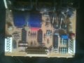
I'm working on a Solar wire feed welder. The control circuit board is always on high wire speed and high voltage setting. I found a replacement board for $200. It has one component that looks burnt. It is a TO 220 package semiconductor. I can't read the number due to the damage. Is there a way to guess what component as a replacement? I can get more model info but I doubt there is a schematic available for this particular board.

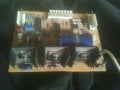
I am familiar with very basic electrical systems but lacking in constant voltage / constant current supplies work. This small circuit board controls a solid state relay to energize the transformer. It also controls wire speed (easy enough) and welder output voltage. How does a low wattage tiny pot control the voltage and the circuit board stabilize the voltage while it is welding? The secondaries go to a bridge diode rectifier then to the load. It does have an inductor coil. I do not see how any of them are variable. How does it work?
Thank you, hoader
 

Reloadron

Joined Jan 15, 2015
7,501
Without a drawing or at least a good detailed picture of the board and component there is no way to tell what it might be. Is there a board designation beside it like VR1 or Q1 or something?

The small tiny pot could be phase firing a SCR to control the voltage. There are plenty of ways tiny pots can make big things happen.

Ron
 

Thread Starter

hoader

Joined Mar 27, 2015
29
Hi:
Sorry it took months for me to respond. Both my tower and laptop died and didn't have a way to write back.
I traced the problem to a circuit control board One of the 3 main transistors in a TO220. The middle one is crispy and no lettering is left. I need to identify and replace the burnt component. I see no center-taps and I believe the solid state relay is either on or off. It has a very simple transformer. 2 wires go to the trigger, 3 wires to the pot on the speed control, 3 to the pot for the voltage control, 2 wires to the solid state relay, and 24 volts AC to power the board. The 24 volts comes from a separate transformer.

I have included some low quality pictures of the board from different angles. Even though I used a low power magnifier, I had trouble seeing what components are connected to the trace or bypassed. I tried my best using Autocad to make a duplicate of the circuit. I tried my best yet some of the connections are guesses and I got lost in portions of the circuit board (nmad dyslexia).

I hope this is enough information to identify the crispy chip. A MIG is soooo much nicer to use than a buzz box and I have up-side-down welding to do. Thank you for your time and effort.

hoader

P.S. How do I upload my DWG file?
 

Attachments

Reloadron

Joined Jan 15, 2015
7,501
Nice job on the drawing of the board. A schematic would be nice. Well you know you have one toasted component. My best guess is maybe a MOSFET in a TO220 case. The problem with an obviously toasted component is why did it toast? The wire feed motor obviously runs, albeit full speed. You can remove the toasted component and see what the wire feed motor does? Assuming it is a MOSFET with it removed and no motor load we could maybe look at the gate signal.

Ron
 

tcmtech

Joined Nov 4, 2013
2,867
I used to work at a local welding supply store and have loads of Solar welder schematics archived so If you can get a model number I can probably track down a full schematics for your machine and control board.

Most of their $200 control boards take about $10 - $20 in actual parts and are very easy to repair if you have any electronics abilities at all.
 

Reloadron

Joined Jan 15, 2015
7,501
Max, you got me? Here is a screen shot open in TrueView of some of what I get. I can rotate the image in TrueView and get a mirror image and other views.

True View 1.png

Ron
 

Thread Starter

hoader

Joined Mar 27, 2015
29
I used to work at a local welding supply store and have loads of Solar welder schematics archived so If you can get a model number I can probably track down a full schematics for your machine and control board.

Most of their $200 control boards take about $10 - $20 in actual parts and are very easy to repair if you have any electronics abilities at all.
There is a number on the board, REL2994 004
 

Thread Starter

hoader

Joined Mar 27, 2015
29
[QUHeadroomHeadRoom, post: 857118, member: 212212"]Any chance you could save it in acad2006 format.?
Max.[/QUOTE]
Mr Heaxroom - one of my favorite charactors . Autocad could have made a strange format of the drawing I sent. If that happened, it was without my permission.
 

Thread Starter

hoader

Joined Mar 27, 2015
29
Hi:

This is from a posting from several months ago. I have a couple new things to add but keeping the original in case the thread has to be restarted. I may have made corrections to the pcb drawing since the first posting. I flipped the pcb drawing up side down so the writing on the bottom view would be readable.

I traced the problem to a circuit control board One of the 3 main transistors in a TO220 package. The middle one is crispy and no lettering is left. A friend of mine replace the burnt component with one he believes is the same. The welder behaves the same with or without the crispy's replacement. The board has 3 chips. The first one is blank – second is MC14093BCP with FBV9402 – third is LMT339N with XXAA9320. One chip is a quad logic gate and quad comparator. Here is the setup of the control board. 2 wires go to the trigger, 3 wires to the pot on the speed control, 3 to the pot for the voltage control, 2 wires to the solid state relay, 2 wires for the gas solenoid and 24 volts AC to power the board. The 24 volts comes from a separate transformer.


Welders I am familiar with has center-taps or moving iron cores in the transformer; this one has none of that. I believe the solid state relay is either on or off pulsing at different frequencies to vary the output voltage. It has a strange transformer with 2 primary winding (via connector) and a center tap on the secondary's. It has 2 diodes for center tap rectification however my understanding of the welding circuit stops there. I included a drawing in Autocad of the welder schematic. The diodes go to an RC circuit that is in parallel with the center tap. Then it goes to a choke. I do not understand how this works. How does the strange transformer, RC circuit, and choke work together?

I have included some low quality pictures of the board from different angles. Even though I used a low power magnifier, I had trouble seeing what components are connected to the trace or bypassed. I tried my best using Autocad to make a duplicate of the circuit. I tried my best yet some of the connections are guesses and I got lost in portions of the circuit board (nmad dyslexia).

Hoader
 

Attachments

Top