Wearable EEG schematic review

Thread Starter

Ilua_S

Joined Apr 2, 2025
11
Hello everyone.
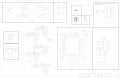
I’m designing a pcb for a wearable eeg device. It’s based on ads1299 adc and stm32wb55cgu6. Data sheets are included. ads1299-stm32 communication is spi full duplex (cs2 is reserved for a daisy chain connection), stm32 has a on board Bluetooth chip that I’m going to utilise for a wireless communication between pcb and PC/mobile. For antenna I chose a chip antenna. Power supply is a battery with voltage converters (+3.3, -3.3, +2.5, -2.5).

I don’t usually ask for help but this project will be sponsored, so I need an extra review from the experts to prevent some ridiculous things from happening.
If you have any advice/recommendation about my schematic, share your thoughts, please. I would be extremely grateful for your help!
 

Attachments

schmitt trigger

Joined Jul 12, 2010
2,027
Question; what type and capacity is the battery?

My only comment would be that for battery-supplied devices the current drain is a very important parameter. Have you actually measured it?

You don’t seem to be applying current consumption-reducing strategies. There is a reason that low dropout regulators have enable inputs, to reduce the current drain when certain functions are not being used.

I also see that you are using Schottky diodes for O’ring the USB and battery supplies. For the battery side I would use a P-Mosfet instead. But again it depends on the battery.
 

Thread Starter

Ilua_S

Joined Apr 2, 2025
11
Question; what type and capacity is the battery?

My only comment would be that for battery-supplied devices the current drain is a very important parameter. Have you actually measured it?

You don’t seem to be applying current consumption-reducing strategies. There is a reason that low dropout regulators have enable inputs, to reduce the current drain when certain functions are not being used.

I also see that you are using Schottky diodes for O’ring the USB and battery supplies. For the battery side I would use a P-Mosfet instead. But again it depends on the battery.
thank you for your comment.
I haven’t decided yet what battery to use but it would be li-ion/li-pol batteries. 3.7v would be enough, I guess. Capacity of >1000mAh should be sufficient for the prototype.
I haven’t thought of current consumption reduction, but it seems reasonable. Should I implement it simply connecting stm32 gpio pins to these enable pins on converters?
 

Thread Starter

Ilua_S

Joined Apr 2, 2025
11
What's your experience of eeg and have you successfully implemented eeg in another way previously?
I have an basic knowledge of physiology of a process and currently writing a paper on eeg based wearable device. I tested everything in modules (amplification, filtering, adc) and now I’m making a stripboard.
This thread is about a parallel project. Quite irrational, You‘d say, and I wouldn’t deny that…
 

Irving

Joined Jan 30, 2016
4,996
The ADS1299 is a great chip but it can only go so far. Circuit layout is extremely critical and a 64pin chip isn't for the faint-hearted! Unless you get the input side right, with proper layout and guarding on at least a 4-layer PCB, you'll not get reliable and repeatable results... And then you want to put an RF generator next door... Well good luck on that one...be prepared for a world of pain getting it to work.

For the record, we implemented a 64 channel implantable device using that chip a few years back. It worked, eventually, but let's just say that was 9 months I'd rather not repeat!
 
Last edited:

Thread Starter

Ilua_S

Joined Apr 2, 2025
11
The ADS1299 is a great chip but it can only go so far. Circuit layout is extremely critical and a 64pin chip isn't for the faint-hearted! Unless you get the input side right, with proper layout and guarding on at least a 4-layer PCB, you'll not get reliable and repeatable results... And then you want to put an RF generator next door... Well good luck on that one...be prepared for a world of pain getting it to work.

For the record, we implemented a 64 channel implantable device using that chip a few years back. It worked, eventually, but let's just say that was 9 months I'd rather not repeat!
As for the schematic, I used OpenBci board and ads1299 official eeg board as references. I tried to research everything I doubted.
 

Thread Starter

Ilua_S

Joined Apr 2, 2025
11
As for the schematic, I used OpenBci board and ads1299 official eeg board as references. I tried to research everything I doubted.
I'm going to make a PCB layout next. I'm aware of basics like analog/digital areas separation, traces width nuances. But the RF part is still pretty hard to comprehend, so I decided to go with the antenna datasheet reference again. I understand that it probably won't work perfectly if proper impedance matching isn't done but for a prototype it would be enough.
The thing about implantable chip sounds intriguing. What was the problem with that device?
I would appreciate it if you could give me some insights about designing such devices. Many thanks!
 

Attachments

tdengineer

Joined Oct 21, 2025
36
As for the schematic, I used OpenBci board and ads1299 official eeg board as references. I tried to research everything I doubted.
I'm going to make a PCB layout next. I'm aware of basics like analog/digital areas separation, traces width nuances. But the RF part is still pretty hard to comprehend, so I decided to go with the antenna datasheet reference again. I understand that it probably won't work perfectly if proper impedance matching isn't done but for a prototype it would be enough.
The thing about implantable chip sounds intriguing. What was the problem with that device?
I would appreciate it if you could give me some insights about designing such devices. Many thanks!
Lol im literally building the exact same thing with the same parts. Just finished the spi now im tryna make sure i get the bias out stuff right
 
Top