Facebook
 Google
 GitHub
 Linkedin
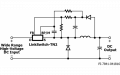
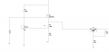
Hi I have been trying reduce from 115Vac to 15Vdc to power a chip. I have found some cleaver methods like the one i am have attached with drops it down to 15V(to power a chip not shown) and also then be dropped further to 5V for other components. I am getting 36mA into the drain and so when I test the actual circuit the MOSFET is getting hotter than Id like. I need atleast 20mA to power an LED down the line which is why I dont drop the amperage.
I just wanted to put this out there to see if anyone had so more cleaver methods I can try. Space is definately the main issue here as I need to fit into a space 31mm by 50mm by 22mm so I cannot use transformers or inductors that are large enough for buck converters.
thanks!
I just wanted to put this out there to see if anyone had so more cleaver methods I can try. Space is definately the main issue here as I need to fit into a space 31mm by 50mm by 22mm so I cannot use transformers or inductors that are large enough for buck converters.
thanks!
Attachments
-
 35.4 KB Views: 32