Want to make a counter that will stop taking clock pulse if count is 3.

Thread Starter

sabbirwasif27

Joined Mar 31, 2023
8
I want to build a counter and want to display it with 7 segment display. I will use a push button to give a clock pulse so this will be the enter button. What I want is, when the counter is 3 then it will lock my clock pulse or enter button. This means if I click the push button after count 3 it won't increase the counter or reset it. It will activate my buzzer and won't stop as long as I do not reset it.
So there will be a reset button to reset my counter. So when I click the reset button the counter will be reset to 0 and by enter button will work again.

Screenshot 2023-04-01 at 1.29.01 AM.png
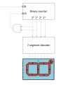
This is my schematic diagram. Here the reset button is working fine but when the counter is 3 it is resetting after clicking the enter button too. I've used much logic to prevent the pulse but could not find the solution.
 

Thread Starter

sabbirwasif27

Joined Mar 31, 2023
8
Whats your thinking about why U3A combines the F & G outputs from the counter?
Actually, I don't know. But as the output from U3A is resetting my counter so I think it is giving 1 while the counter is 3. I saw a YouTube video about how to make a mod 4 counter. But I've no idea about the process. Because I'm not familiar with this IC. I just want to make a counter and display it with reset and prevent auto reset functionalities. Can you help me with this?
 
Last edited:

Irving

Joined Jan 30, 2016
3,899
Actually, I don't know. But as the output from U3A is resetting my counter so I think it is giving 1 while the counter is 3. I saw a YouTube video about how to make a mod 4 counter. But I've no idea about the process. Because I'm not familiar with this IC. I just want to make a counter and display it with reset and prevent auto reset functionalities. Can you help me with this?
I thought that was the case. You're assuming that F & G represent the binary value for 3, but they don't, they are the segment drives for segments F and G on the display, nothing directly to do with the actual value of the counter.

To make that work you need a different counter:

1680294244467.png

Or, as suggested above, decode the segments that represent the number you want to stop at.
 

Attachments

Last edited:

crutschow

Joined Mar 14, 2008
34,470
To make this work you need a different counter:
Not necessarily.
Why can't you just determine the segments that will cause the counter to stop at the desired number?
I think two unique segments would work to stop at 3 when counting up from 0.
 

LesJones

Joined Jan 8, 2017
4,191
You only need to think which segments are lit (And therfore which segment drive outputs are high. ) as it counts up from zero. What digit is displayed (Counting from zero) when both the F and G segments are lit. And then think what happens when that digit is displayed in the schematic in post #1.
As already pointed out you are NOT blocking clock pulses to the counter. You are resetting it back to zero.

Les.
 

ElectricSpidey

Joined Dec 2, 2017
2,786
Segments "G" and "C" can be ANDed to stop the count, with the output connected to the INH pin instead of MR.

Assuming a common cathode display.

And the gate will need pulldown resistors if its only source current available from the decoder. (see below)

1680299284121.png
 
Last edited:

ElectricSpidey

Joined Dec 2, 2017
2,786
Ok after looking at the 4026 data sheet I see the outputs do go both low and high, so no pulldown resistors needed.

But I also want to note the limited current available from the outputs of the chip, so be sure to restrict the current.

I'm not too sure this chip is designed to directly drive 7 segment displays, but many modern displays can use much less current.

In the real world you will probably need some de-bounce on the clock push button.

This doesn't really mean anything but if you had built that circuit in real life and pushed the reset button when the AND gate was LOW bad things might happen.
 
Last edited:

Thread Starter

sabbirwasif27

Joined Mar 31, 2023
8
I thought that was the case. You're assuming that F & G represent the binary value for 3, but they don't, they are the segment drives for segments F and G on the display, nothing directly to do with the actual value of the counter.

To make that work you need a different counter:

View attachment 291211

Or, as suggested above, decode the segments that represent the number you want to stop at.
Can you tell me what counter is it? I mean what is its IC number?
 

LesJones

Joined Jan 8, 2017
4,191
You can do what you require using your existing counter/ decoder chip
These are tye steps.
1 / Decode the segment drive outputs using your 2 input AND gate. The output of the and gate will go high when the display is showing 3. (I will leave you to work out how to decode for state 3 instead of state 4.)
2 / insert an AND gate in the clock signal so it only allows the clock signal though when the other input on theis AND gate is high.
3 / Use an inverter IC (Such as a CD4009.) to invert the output of the AND gate in step 1
4 / connect the output of the inverter to the aubconnected input of the and gate in step 2

You are using a mix of logic families so there could well be a problem with the 4000 series device driving the inputs of a 74 series device. You should use a CD4081 in place of your 7408.
Is your question related to homework or school project ?

Les.
 

Irving

Joined Jan 30, 2016
3,899
2 / insert an AND gate in the clock signal so it only allows the clock signal though when the other input on theis AND gate is high.
3 / Use an inverter IC (Such as a CD4009.) to invert the output of the AND gate in step 1
4 / connect the output of the inverter to the aubconnected input of the and gate in step 2
These steps are not needed. The output of AND gate decoding segments goes high, connected to Clock Inhibit, stops counting, until reset.
 

Reloadron

Joined Jan 15, 2015
7,523
This is an old thread you may want to read.

What you seem to be after is a "Count To N and Halt". Your N is 3. What I linked to is a 4017 Decade Counter/Divider so it is not driving a 7 segment LED. The idea is you want to count to N and halt. Your best choice is a counter which can inhibit the input clock or you add a gate to inhibit the clock.

Ron
 

Irving

Joined Jan 30, 2016
3,899
Can you tell me what counter is it? I mean what is its IC number?
You would need a CD4024 7-stage counter plus a CD4511 seven-segment decoder. However, the CD4024 doesn't have a clock inhibit input so you would need extra logic to 'stop the clock' as previously discussed. There are several ways to deal with that.

Also, in the real world, a push button will give several pulses due to contact bounce - you need a solution to that as well. One solution is to use a 555 timer chip to remove the 'bounce', as shown below... which also solves the clock inhibit requirement...

In this simulation the push button X1 is pressed 5 times, each time for about 0.1sec (bottom, pink trace). Each time it is pressed, the 555 creates a single 0.25 sec pulse (red trace) until the count gets to 3 (q0 & q1 = 1, green & blue traces) at which point the output of the NAND gate go low which prevents the 555 generating any more pulses until the reset button X2 is pressed. The resistor R3 and capacitor C2 provide a simple power on reset to make sure the counter is reset to zero when the power is switched on.

1680357824360.png
 

LesJones

Joined Jan 8, 2017
4,191
Hi Irving, Re post #17 you are correct. I had not looked at the datasheet for the CD4026 so I did not realise it had a clock inhibit input. The TS still needs to change the decode of the segment pattern from 4 to 3. The circuit that he followed will count to 3. The next clock pulse will take it to 4 but that will set it back to zero after a few microseconds.
 
Top