Volume control for mono amp

Thread Starter

Yesm8

Joined Apr 20, 2016
13
Hello you wonderful geniuses,

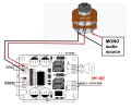
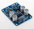
I am a noob trying to do a mono amp project.
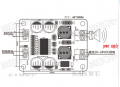
I have this mono amp from aliexpress.
http://nl.aliexpress.com/item/TPA31..._6&btsid=ed7cabf6-a08f-49e9-a4e3-bed400a07e34

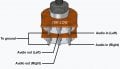
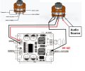
I want to add a volume control to it. As far as I've been able to figure out I'll need a (10k?) potentiometer.
I am unable to find a clear wiring schematic but am also unaware of the do's and dont's of difference in resistance.

I am reasonibly handy and did have a near perfect score in high school for an electrical class. (wow!)

I'm thinking these will help me: http://nl.aliexpress.com/item/10-PC..._6&btsid=72a0147e-f4d6-4b29-bfd8-b867b81e60e8

Can somebody point me towards how I should solder such a thing to the board, perhaps the why or point me towards a thread, project where I can clearly see what I'm supposed to do and perhaps learn about the why?

Thanx legends
 

Attachments

GopherT

Joined Nov 23, 2012
8,009
Don't use that pot. You need one with a LOG or AUDIO taper. The one shown is a LINEAR taper. It will seem like its very sensitive. For part of the turn and then like it does nothing the rest of the turn.

image.jpg
 

Thread Starter

Yesm8

Joined Apr 20, 2016
13
I've learned that I need a logarithmic potentiometer due to the logarithmically scaled human perception of sound pressure levels.
I'm thinking about going for these 10k ones: http://nl.aliexpress.com/item/Free-..._6&btsid=487d2bab-1967-4733-94a6-1ce8428e6a30
(thank you for the suggestion but the free shipping and prices of aliexpress are far better than on ebay)

I've found a quite clear potentiometer pin wiring picture.
As I'm too noob for electrical schematics I'll save you the agony and go for a sort diagram to show you what I'm thinking of doing.
I recon this could work a couple of questions remain:
How can I calculate or know whether the 10.000 Ohm Potentiometer is good or whether I'd need a 100.000 Ohm Potentiometer?
Should I perhaps use the potentiometer to attenuate the OUTPUT of the amplifier instead?
Is wiring the ground pins of the potentiometer to the negative of the power source what is meant by wiring to signal ground?

Thanx for the help
 

Attachments

GopherT

Joined Nov 23, 2012
8,009
I've learned that I need a logarithmic potentiometer due to the logarithmically scaled human perception of sound pressure levels.
I'm thinking about going for these 10k ones: http://nl.aliexpress.com/item/Free-..._6&btsid=487d2bab-1967-4733-94a6-1ce8428e6a30
(thank you for the suggestion but the free shipping and prices of aliexpress are far better than on ebay)

I've found a quite clear potentiometer pin wiring picture.
As I'm too noob for electrical schematics I'll save you the agony and go for a sort diagram to show you what I'm thinking of doing.
I recon this could work a couple of questions remain:
How can I calculate or know whether the 10.000 Ohm Potentiometer is good or whether I'd need a 100.000 Ohm Potentiometer?
Should I perhaps use the potentiometer to attenuate the OUTPUT of the amplifier instead?
Is wiring the ground pins of the potentiometer to the negative of the power source what is meant by wiring to signal ground?

Thanx for the help

No. Your picture shows a Double potentiometer.

Look at post #2. You only need a single potentiometer (3 pins).

Starting with the two signal wires from your source. Send both to the outside two pins on your potentiometer. Then a second pair of wires from your potentiometer (center to signal in) and left to other signal in.


Then Signal into the left right pin. Signal out of the center pin to you board
 

Thread Starter

Yesm8

Joined Apr 20, 2016
13
No. Your picture shows a Double potentiometer.

Look at post #2. You only need a single potentiometer (3 pins).

Starting with the two signal wires from your source. Send both to the outside two pins on your potentiometer. Then a second pair of wires from your potentiometer (center to signal in) and left to other signal in.


Then Signal into the left right pin. Signal out of the center pin to you board
Oh wow... The pin connecting picture and lack of single potentiometers on Aliexpress completely made me forget about the fact I'm going for mono...
But I should be able to wire everything to one of the two rows of pins on a double potentiometer shouldn't I?
I can't seem to find any affordable single logarithmic potentiontiometers.
Thank you for the input.
Any pointers as to whether the 10K potentiometer being the right resistance or perhaps 100K (or otherwise) being more appropriate?
Do you perhaps have an idea what the "MUTE" solder connections next to the audio inputs would be used for?
Then my setup should work as followed shouldn't it?
 

Attachments

GopherT

Joined Nov 23, 2012
8,009
The 10k should be fine assuming that your input source is a pre-amplifier of some sort. If, however, your input source is some very delicate signal like the pick-up from a guitar or an un-amplified microphone, then 10k is not a great option. You could try a 100k but guitars generally sound best with 250k to 2M but they does not work well with this amplifier so I would recommend a preAmp for those.
 

Dodgydave

Joined Jun 22, 2012
11,285
100k will give you a higher input resistance when connecting to an audio source like a microphone, 10k would be ok for connecting to a mobile phone or mp3 player, the mute will shut the speaker output down instantly, instead of turning down the volume.
 

Thread Starter

Yesm8

Joined Apr 20, 2016
13
100k will give you a higher input resistance when connecting to an audio source like a microphone, 10k would be ok for connecting to a mobile phone or mp3 player, the mute will shut the speaker output down instantly, instead of turning down the volume.
My plan is to make a multi-zone, amplifier project box with 6 of these little amps to drive garden speakers.
I'd probably be using this little Dutch made DAC I have. http://ifi-audio.com/portfolio-view/nano-idsd/
My next campaign in this quest would be finding out how to build something like this: http://www.juno.co.uk/products/monacor-smc1-stereo-mono-converter/432335-01/
A stereo to mono converter because I don't like to shell out the cash for it when I apparently could achieve the same with a few carefully wired resistors (to be examined).
And another difficult part would be how to power the entire thing with a single adapter and wire it of course.
 

crutschow

Joined Mar 14, 2008
34,285
In case it easier to get a standard pot, here's my write-up on using a standard pot to give an approximate log taper.
I suggest a 100kΩ linear pot with a 10kΩ compensating resistor across the pot output.
 

Thread Starter

Yesm8

Joined Apr 20, 2016
13
Could anybody tell me the real world difference between using a 10K and a 100K potentiometer in my configuration?
From what I hear the higher resistance would make it less prone to distortion. But does it also inhibit detail resolution at lower volumes perhaps?
Given that my signal would be a very clean DAC source and flac audio files perhaps 10K potentiometers is the way to go?
GopherT told me that a pre-amp should work with the 10K potentiometers. The DAC has a volume control of it's own which works with the RCA outputs so that pretty much covers the "pre-amp of some sort" part I guess.
I'm interested in your suggestion Crutschow but if I can use the 10K potentiometers perfectly fine then I don't wish to complicate things further.
 

GopherT

Joined Nov 23, 2012
8,009
A potentiometer is a voltage divider. It divides the input voltage into two signals with lower intensity. Whether you divide the signal with 100k or 10k it doesn't really matter on the divider part. If the wiper (moving part) is at the half way point of either potentiometer, you end up with half the voltage. That is fine and dandy if no current (or extremely small amounts) of current flow from the wiper to your amplifier. But, if some amount of current is needed (in your case, up to 50 microamps is listed as the max input current draw), then a 100k ohm resistor blocking a 1.4V (ground to peak) signal would be 14 microamps and the sound quality would start to fall to crap. If you use a 10k pot, you can deliver 10x the current.

also, the higher the potentiometer resistance, the more noise you generally have, and the more current amplification you need (if the input is not a FET-based device).

10k will be perfect. Such an inexpensive pot that you have selected may sound scratchy when you change the volume. just a guess based on the price point. It may work perfectly well.

Also, a good audio pot should offer several decades of resolution. That is, each quarter turn should offer something like 3-10 ohms, 10 to 100, 100-1000 and 1000-10k. Very inexpensive pots tend to have some defect or cheapness like...
- only 1.5 to 2.5 decades of resolution (300-1000 and 1000 to 10k) with a sudden jump from 0 to 300 or 10k for a quarter of a turn
- static/sratchy noises while moving
- dead spots as you turn (zero ohm or infinite ohms)
-
 

crutschow

Joined Mar 14, 2008
34,285
.......................
I'm interested in your suggestion Crutschow but if I can use the 10K potentiometers perfectly fine then I don't wish to complicate things further.
The reason I suggested a 100kΩ pot is because the 10kΩ resistor from the pot wiper to ground to get the quasi-log taper will mean the output impedance is always less than 10kΩ, which should cause no distortion or loading problems.
(Actually I see that I recommended 15kΩ for the resistor not 10K.)
If you use a 10kΩ pot with a 1.5kΩ resistor from the wiper to ground (to get the same quasi-log output) then the minimum resistance to the source would be 1.5kΩ with the volume at maximum, which may be too low a load impedance for the source.

But you can certainly try a 10kΩ pot with a 1.5kΩ resistor to see if it works okay.
You could probably go to 2kΩ or so for the resistor and still get a reasonable adjustment taper.
 

Thread Starter

Yesm8

Joined Apr 20, 2016
13
I thank you all for your input.
I will breed on the project further and perhaps (if I don't forget) update when I'm making progress.
 
Top