Voltage stabilizer working principle

MisterBill2

Joined Jan 23, 2018
27,838
Certainly a tap changer can stablize a voltage. THAT is what I described. A VOLTAGE REGULATOR is quite different, in that it would hold the voltage at a preset level. A "constant Voltage Transformer" can do that quite well over a limited range.
A "tap changer" scheme can easily cover a broader range, and can have a much greater power handling capability.
The "tap changer" is not a voltage regulator, though. It IS quite efficient, and they do not produce a lot of heat. A "Constant Voltge " transformer, is much less efficient, but it does provide actual regulation within limits. The CVT uses a saturated core to assure that the magnetic flux is always at the same level, thus producing the fairly constant voltage. THEY ALWAYS RUN HOT, and that heat represents the wasted power.
 

B-JoJo-S

Joined Jan 3, 2026
407
Well, the TS didn't specify what type of system he wanted information on. He merely asked where the makeup voltage came from. In a CVT it comes from the ferroresonance of the transformer. In a switcher it comes from changing taps.
 

Irving

Joined Jan 30, 2016
5,195
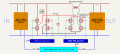
Vihaan's question arose from a project he's writing software for, where he's been provided some hardware schematics and a block diagram of the stabilization control loop. I've reproduced a simplified version below. His question reflects the paucity of the information provided and his relative inexperience regarding hardware, and specifically power control systems. Also I think English isn't his native language. So we can excuse the naivety of his question.
1782930840887.png

And yes, I know the gates are tied together, this is conceptual, not a full schematic!
 

MisterBill2

Joined Jan 23, 2018
27,838
That is quite an interesting concept for adding or subtracting voltage. with the series transformer. My guess is that it will add some high frequency to the output.
 

MisterBill2

Joined Jan 23, 2018
27,838
By "interesting concept" Imean that I had not thought about it using that scheme. I like it, certainly it is less complex and simpler than what I had been considering. But it is not so obvious BECAUSE it is quite different.
I do like the concept!!
 

ronsimpson

Joined Oct 7, 2019
4,738
Voltage stabilizer working principle
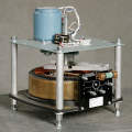
The first, way I stabilized the line voltage used a very large variable transformer something like this. I connected a motor to the shaft. If the voltage was 3% too high or 5% low the motor turned the shaft getting the line voltage back to right.
1782961480507.png
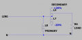
The second way I have used: We used a small variable transformer that made +20% of line voltage and -20% of line voltage. If the live voltage was wrong the secondary was adjusted. Because the transformer only carried 20% or less of the line power the transformer was small. If the input line voltage was correct the transformer carried no power.
1782962198186.png
 

MisterBill2

Joined Jan 23, 2018
27,838
The variable transformer DOES NOT "stabilize" the AC voltage, instead, it allows it to be adjusted manually. By itself it does not correct for any changes.

I make this statement to avoid giving folks the incorrect impression that the variable transformer, (VVT),makes a correction automaticly, similar to a voltage regulator circuit. It DOES NOT do that!
A "VVT" is a handy tool for quite a few different uses, but without the addition of a servo-motor and additional electronics it is not a stabilizer, but only an adjustment tool. THAT is quite a difference. It requires a human and human judgement in the feedback loop to provide any stabilizing function.
 

Ya’akov

Joined Jan 27, 2019
10,263
@Danko's answer is correct but I think it was lost in the fog of other answers.

An old-fashioned, multi-tap transformer-based stabilizer uses a transformer and so the answer to the TS' question is simple. Nothing is being created. The transformer will trade off voltage for current capacity and some heat.

Thus, if the stabilizer has been properly specified, nothing will be lost at the output—the current will remain the same but the maximum (and unused) capacity for current will diminish.

If the stabilizer is improperly specified then in theory the maximum current could be reached when the tap is switched for higher voltage. In practice, given the range of adjustment available (small), you would have to be running even the normal taps at near capacity.

BOTTOM LINE: Where does the extra voltage come from? It comes from the extra current capacity in the input to the transformer and the extra capacity of the transformer itself.
 

ronsimpson

Joined Oct 7, 2019
4,738
By itself it does not correct for any changes.
I was not clear; I used voltage comparators and relays to drive a motor that adjusted the transformer. There is a closed loop.
This is not my design but looks close.
1782995872823.png
Years ago a company paid me to fine the design flaw in a solid-state version of this.
 

MisterBill2

Joined Jan 23, 2018
27,838
The "extra" 30 volts in an AC voltage regulation scheme comes from a higher voltage tap on the transformer.
Look closely at the circuit on the terminal board of the VVT in post #32! There are taps higher than the one used for the mains input voltage. That is a standard feature on most 'POWERSTAT's and 'VARIACs'.
 

Thread Starter

Vihaan@123

Joined Oct 7, 2025
288
I really like the mathematical calculations for me to understand the theory like input voltage, input current, output voltage, output current, which is supplying how much, if anyone can show me that it will be interesting.
 

Ya’akov

Joined Jan 27, 2019
10,263
I really like the mathematical calculations for me to understand the theory like input voltage, input current, output voltage, output current, which is supplying how much, if anyone can show me that it will be interesting.
Do you understand the operation of a transformer?
 

MisterBill2

Joined Jan 23, 2018
27,838
Consider that a regulated battery charger is based on a feedback loop type of system, which certainly has an interesting "transfer function" that is mathmaticly quite interesting.
It samples the battery voltage , compares that to a known reference, and calculates the error. At that pointit may decide to charge, and it might even decide how much to charge. So there you have both LOGIC and MATH. What more could you ask for???
 

MrChips

Joined Oct 2, 2009
34,974
I really like the mathematical calculations for me to understand the theory like input voltage, input current, output voltage, output current, which is supplying how much, if anyone can show me that it will be interesting.
Do you know the math for any control system?
 
That "math", the "transfer function" as our one instructor called it, becomes rather complex when you get beyond the basic theory of the functioning. In addition, if any portion of the loop is not linear, that adds to the complexity.
Without any doubt, the second and third semester feedback systems courses were the most complex part of my college education classes..
 
Top