Voltage stabilizer working principle

Thread Starter

Vihaan@123

Joined Oct 7, 2025
288
I have basic question on the voltage stabilizer working principle, the role of stabilizer is to keep the output voltage fixed at suppose 230V even if the input is at lower level. Suppose if the input is 200V how the stabilizer is able to get the additional 30V?
 

Danko

Joined Nov 22, 2017
2,199
Suppose if the input is 200V how the stabilizer is able to get the additional 30V?
https://electrosheriff.com/useful-a...CZ1OW9lt4vBl1-kvpQLKJUs3tMNu2NWQ15If8qXRODr2V
How does a voltage stabilizer correct voltage? Step by step analysis

A voltage stabilizer, also known as a voltage regulator, is an electrical device designed to maintain a stable voltage level in an electrical system despite fluctuations in the input voltage. The primary function of a voltage stabilizer is to ensure that the output voltage remains within a specified range, providing a consistent and reliable power supply to connected electrical equipment.

The working principle of a voltage stabilizer involves the use of a control circuit that continuously monitors the input voltage. When the input voltage deviates, the stabilizer takes corrective actions to adjust and stabilize the output voltage. There are different types of voltage stabilizers, including servo-controlled stabilizers and solid-state electronic stabilizers, and their working principles may vary. Here, we'll provide a general overview of how a typical servo-controlled voltage stabilizer works:

Sensing the Input Voltage:
The voltage stabilizer is equipped with a voltage-sensing mechanism, such as a potential transformer, that continuously monitors the input voltage.

Comparison with Reference Voltage:
The sensed input voltage is compared to a reference voltage, which represents the desired or specified output voltage level. This reference voltage is set based on the requirements of the connected equipment. In SUNTEK stabilizers it is 220 Volts or 230 Volts

Error Detection:
The difference between the sensed input voltage and the reference voltage is referred to as the error. The control circuit detects this error signal.

Control Circuit:
The control circuit processes the error signal and determines the corrective action required to bring the output voltage back to the desired level.

Actuator or Servo Motor:
In a servo-controlled stabilizer, an actuator or servo motor is employed to adjust the position of a variable transformer or an autotransformer. The servo motor moves the transformer's tap position, altering the turns ratio and, consequently, the output voltage. In relay stabilizers, additional parts of the coil winding are connected (each relay is responsible for its own small segment of the coil).

Voltage Correction:
The movement of the transformer tap position corrects the voltage error. If the input voltage increases, the stabilizer reduces the output voltage by adjusting the tap position, and vice versa.

Stabilized Output:
The stabilizer continues to make real-time adjustments to the transformer tap position, ensuring that the output voltage remains within the acceptable range despite fluctuations in the input voltage.

Overload and Overvoltage Protection:
Many voltage stabilizers are equipped with protective features such as overload protection and overvoltage protection to safeguard connected equipment from electrical anomalies. For example, SUNTEK voltage stabilizers operate at very high temperatures up to 50 degrees or very low temperatures down to minus 30. And if there is a thunderstorm in your region, don’t worry - lightning protection is already built into the basic version of the voltage stabilizer.

In summary, a voltage stabilizer maintains a stable output voltage by continuously monitoring the input voltage and making adjustments as necessary. This helps protect sensitive electrical and electronic equipment from damage caused by voltage fluctuations.
 

Thread Starter

Vihaan@123

Joined Oct 7, 2025
288
But if i am generating the additional 30V more, the output power is more than the input power, does it do by reducing the output current? Does the energy principle is satisfied?
 

Danko

Joined Nov 22, 2017
2,199
But if i am generating the additional 30V more, the output power is more than the input power, does it do by reducing the output current? Does the energy principle is satisfied?
Voltage stabilizer increase current from input voltage source to increase output power.
Input power always is bigger than output power.
 

B-JoJo-S

Joined Jan 3, 2026
405
To answer adequately we have to make some assumptions. My first assumption is that you're talking about 230VAC. Second assumption is that it's 50 or 60Hz. Assuming this is the case, drawing from personal experience, I have a Ferroresonant transformer that stabilizes the AC voltage at 120VAC. Yes, I'm sure you can find them for 230VAC as well. In the case of the FR transformer it reduces spikes in voltage, maintaining a very close output value to what it's designed for. In the case of brown-outs (drop in line voltage) it can maintain a very close output value, only dropping slightly.

The kind of regulator @Danko might be thinking of is a regulator that limits the output voltage such as a 12 volt (DC) regulated unit. Typically it takes at least 2 volts higher than the final voltage. If the input voltage is 20VDC then to regulate at 12VDC it has to waste about 8V as heat. Depending on the current will determine the wattage and the need for a heatsink. Unfortunately a 12VDC regulator can not increase the voltage from a lower voltage UNLESS the regulator is a Buck/Boost type regulator. In that case at 20VDC is switched on and off very fast (high frequency) where 20 volts is on only 60% of the time resulting in an average of 12 volts output. Should the voltage drop below 12V, at high frequency it can invert the input voltage and boost it before it regulates it at 12V. As for "Power" you can't get more power than is available. There's where the explanation goes beyond my ability to explain. Others will have to chime in on that part, should someone decide to do so.
 

schmitt trigger

Joined Jul 12, 2010
2,147
B-jojo beat me to mention the ferroresonant transformer.
Those were amazing examples of what I call “Paleolithic Electrical Technology”.

I believe that they would still be used today if it weren’t for its two main drawbacks: poor efficiency and being quite massive for the output power.
 

AnalogKid

Joined Aug 1, 2013
12,202
https://en.wikipedia.org/wiki/Voltage_regulator#Constant-voltage_transformer

Unlike a "normal" transformer, efficiency increases with load. Also, this type of stabilizer has a large radiated magnetic field, especially when boosting.

I've got a couple, salvaged from a large TV station routing switcher. +/-8 Vdc at 10 A. With no active regulation, the outputs are surprisingly stable from 50% to 100% load, sitting at around 8.5 V..

ak
 

Thread Starter

Vihaan@123

Joined Oct 7, 2025
288
The voltage stabilizer regulates only the voltage, or does it regulate current also? I wanted to do some calculations if the voltage stabilizer is 2.5KVA and if the input voltage is 230V then the current is 10.86A, if the input voltage comes down to 200V the current supplied by mains is 12.5 Amps (2500VA/200V), the 30V is supplied by stabilizer, how much current does it provide?
 

panic mode

Joined Oct 10, 2011
5,121
you are overthinking it. lets try this interpretation:

imagine 1:1 transformer but with several extra taps at the secondary so that you can choose output voltage that is slightly higher or slightly lower. suppose those output taps are labeled A,B,C,D,E,F and A is 10% lower than input, B is 10% lower, C is equal, D is 10% higher and E is 20% higher. now the problem is simply choosing correct tap to get corrected output voltage. to do that, you can measure voltage and then activate relay that selects correct tap.

when it comes to load current... same idea...do not overthink it. load will draw whatever current it needs. just make sure that your stabilizer can handle it.
 

MrChips

Joined Oct 2, 2009
34,974
The voltage stabilizer regulates only the voltage, or does it regulate current also? I wanted to do some calculations if the voltage stabilizer is 2.5KVA and if the input voltage is 230V then the current is 10.86A, if the input voltage comes down to 200V the current supplied by mains is 12.5 Amps (2500VA/200V), the 30V is supplied by stabilizer, how much current does it provide?
You cannot regulate voltage and current at the same time. The power output is governed by Ohm's Law, i.e. the power output depends on the load that is drawing the power. Voltage and current regulators are actually limiters. They control the maximum voltage or current that can be drawn from the power supply. At any given moment, the power supply is at one of the two limits, either the voltage limit or the current limit.

A voltage stabilizer prevents the voltage from rising above the designed voltage. If the input voltage falls below the designed output voltage, it cannot "make up" the lost voltage. The exception is in a ferroresonant transformer. This is operated in saturation mode which limits the output voltage. When the input voltage falls, there is still some headroom before the transformer comes out of saturation mode.
 

Danko

Joined Nov 22, 2017
2,199
the 30V is supplied by stabilizer, how much current does it provide?
Well, you have stable voltage 30 V, independent on input voltage.
So, max current through load can be 2500 W / 30V =83 A.
Load current (A) is 30V / Rload (Ω).
 
Last edited:

Irving

Joined Jan 30, 2016
5,195
A voltage stabilizer prevents the voltage from rising above the designed voltage. If the input voltage falls below the designed output voltage, it cannot "make up" the lost voltage.
Not necessarily. An AC stabilizer based on a buck-boost inline transformer can increase the output voltage above the input. Its both Power Factor correction and voltage stabilisation at the same time. A synchronous MOSFET-based bridge rectifier generates a HV DC Bus and a high-frequency (50kHz+) MOSFET bridge applies a switched DC signal to the primary of a transformer whose secondary is inline between the live phase input and output ports. By manipulating the low frequency shape of the PWM'd primary signal both input current phase and instantaneous voltage output can be modified in real time. The extra energy comes from the HV DC Bus, so efficiency overall is lower, but the PF correction, depending on load type, can make up for some of that. It only needs 3 identical but independent stabiisers to add 50 - 100VA or so to get 1% stabilisation per phase on a 5kw total 3-phase system.
 

Ramussons

Joined May 3, 2013
1,571
I have basic question on the voltage stabilizer working principle, the role of stabilizer is to keep the output voltage fixed at suppose 230V even if the input is at lower level. Suppose if the input is 200V how the stabilizer is able to get the additional 30V?
Are you referring to the external voltage regulators that you use on a TV/Fridge/Airconditioner....? Those are not voltage regulators in the true sense, they reduce the voltage variations. An input of 180 to 260 Volts is brought down to 210 to 240. These are step regulators and they use a transformer to boost or buck the input voltage.
 

MisterBill2

Joined Jan 23, 2018
27,834
It is not clear to me what actually what the TS is wanting explained in post #1!!
WHAT does the TS want???
There are common VOLTAGE REGULATORS that are mostly direct current output devices, and there are "Constant Voltage Transformers" that will maintain a constant AC output voltage because they operate in a magneticly saturated core mode. Those devices work well but they run "quite warm" because they are not very efficient.
There are also electronicly regulated transformer-type systems that use active electronic systems to control the AC output.
An accurate description of what is required will assist in providing an accurate description of the means to provide it.
Otherwise the result is accurate descriptions that can be good guesses as to just what is actually searched for.

For holding a "fairly constant" mains voltage, I have seen a "tap change" in operation. When the current draw became great enough to pull the area mains supply below a set value, the tap changer would change the connection to the output of the transformer to a higher voltage tap. That works adequately until the transformer MAXIMUM POWER output is reached. At that point, if the required load current rises more, the control logic switches back to a lower voltage tap to LIMIT THE POWER to the load, protecting the transformer.
 
Last edited:

B-JoJo-S

Joined Jan 3, 2026
405
WHAT does the TS want???
Wants to understand how a stabilizer is able to see 200VAC (AC thrown in for clarity); wants to know how the extra 30 volts is generated to bring the 200 back up to 230VAC.
if the input is 200V how the stabilizer is able to get the additional 30V?
That's done by either a Buck/Boost converter or a Ferroresonant transformer. To my knowledge; as deep as a sidewalk puddle; Buck Boost is done with DC voltages and not AC voltages. But what do I know ? !
 

MisterBill2

Joined Jan 23, 2018
27,834
A "tap changer system" could probably correct the 230 volts line dropping dow to 200 volts, by a tap change.
I have also seen a "voltage correction"system that used a variable voltage transformer, similar to a variac, with a servo-motorized drive controlled by some voltage sensing electronics. That controlled the lighting for a portait photography business. That was quite a few years ago, back in 1968. It was in a medical research lab.
 

B-JoJo-S

Joined Jan 3, 2026
405
You're talking about an automatic switching system that changes which tap is used to maintain a certain voltage. I don't know how expensive such a system would be but I'd think it's not cheap. A CVT (Constant Voltage Transformer or Ferroresonant transformer) would maintain a constant output on the secondary side as long as the primary voltage doesn't dip below some threshold. As for OVER voltage on the primary, I think (key word "think") any over voltage would be easily managed to some greater extent. A CVT would just output the target voltage within a certain percentage without having to do any switching. No switches to break down, no voltage spikes, no momentary loss of voltage. Yeah, a Tap Changer System would work but I think that would be overkill. Besides, the TS is merely asking where the extra voltage comes from.
 

B-JoJo-S

Joined Jan 3, 2026
405
Worthwhile read.
https://voltage-disturbance.com/power-engineering/ferroresonant-transformer/
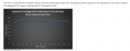
Note that differing loads will respond differently. A CVT with no load will quickly come up to 120VAC at as low as about 37VAC. Notice how the voltage is stable (looking at the chart).
Screenshot 2026-07-01 at 10.44.33 AM.png
In this test the CVT output is about 124VAC when the input is at 120VAC. Of course differing loads will cause the transformer to respond differently. Use the link to see more charts. Hopefully this link will help you understand where the extra voltage comes from.

HOWEVER: keep in mind that voltage isn't everything. The amount of power will vary with different loads. You can't take 40VAC and turn it into 120VAC and use it to run your welder. Not enough "POWER" (watts). Power (watts) is voltage times amperage. If at 40 volts there's not enough amperage then the wattage will be much much lower. It's all in the math.
 

MrChips

Joined Oct 2, 2009
34,974
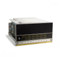
Data General NOVA 2/10 minicomputer used a massive constant voltage transformer to supply +5 VDC to the entire system without using semiconductor voltage regulators. During power brownouts, the room lights would flicker or go dim but the NOVA 2/10 kept on running.

1782924675902.png

We used these constant voltage transformers to power photographic enlargers in the darkroom. It provided colour temperature stability when making colour prints.

1782924342781.png
 
Top