Voltage regulator trouble when powering a wireless router from a battery

Thread Starter

Zurn

Joined Mar 4, 2019
122
Try replacing the battery with your bench power supply see if the problem persists. This will help verify that the battery is the issue. Scope the input and output side of the regulator to determine if there is still a significant voltage sag. The input should not sag at all with the bench supply, and ideally the output side will not either. If the input does not sag, but the output still sags, then that's a sign your regulator is not up to the job.
Ya, I've checked every regulator w/my power supply and they all work instantly. It's definitely a battery issue.

Could it be that batteries just can't supply the stable current necessary to run the router with all the other devices connected - even though the total current draw when everything's active isn't anywhere near the max current the battery system is rated for?
 

crutschow

Joined Mar 14, 2008
38,578
Could it be that batteries just can't supply the stable current necessary to run the router with all the other devices connected - even though the total current draw when everything's active isn't anywhere near the max current the battery system is rated for?
Monitoring the battery voltage should tell you that.
 

ci139

Joined Jul 11, 2016
2,008
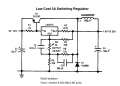
https://www.quora.com/Can-a-7805-regulator-actually-be-used-as-a-switching-converter ( ← it's inefficient and lacks the output S/C current limit but the LM7805 won't likely get that hot as in standalone v.)
https://www.youspice.com/spiceproje...cts/spice-model-of-lm78xx-voltage-regulators/
(alternate see upload or ti-homepage - the least uses likely P-Spice --or-- encrypted model not suitable for outside Tina-ti environment)
fig.18 https://eu.mouser.com/datasheet/2/308/fairchild semiconductor_ka7805ae-1191496.pdf
-----------
a critical net for the buck in question to start/operate is the PNP power switch dependent R.BE value and the zener's parameters (also other than reverse breakdown voltage) . . .
 

Attachments

Last edited:

Thread Starter

Zurn

Joined Mar 4, 2019
122
Interesting... but what suggests these would work given my other dedicated switching regulators don't?
 

ci139

Joined Jul 11, 2016
2,008
if you perform an experiment you log all it's parameters
  • Battery staring voltage initial impedance (internal resistance/ temperature) (voltage drop on short pulse current of near rated max. continuous load-current)
  • during the test battery terminal (voltage) inp current , outp voltage (on load) sink (to load) current
if you have these . . . . you can answer a lot of questions on your own

///
  • the battery may be basically healthy but can't provide the peak current required by switcher -- or -- can't provide it after some minutes of operation (which is unlikely the case for the healthy battery) = pile a load of 470uF 50V in parallel with it -- see if it improves anything (initial balance for BAT capacitors must be through resistor or small wattage 12V light bulb)
    + ↓↓ the big capacitor at either side of swicthng supply may fail the oscillator to start or interfere it's normal op.↓↓
    • ↑↑ so if it's an experiment you need to assume everything may fail = use fuses (and mild loads for starting) ↑↑
    • this is prefferedly done in steps : (with multi-meters you can see the average currents that may be somewhat different from the actual ones . . . . but they likely are precise enough to debug the system)
    • steady supply to router (to find out if router or SMPS has issues)
    • steady (resistive) load to SMPS , increase output current untill the outp voltage starts to drift down from 5V (to get to know the SMPS)
    • steady supply & load to SMPS (to find out if battery is causing the issue)
  • might be also that it's router's internal power (supply) or power to modems (or other involved circuitry) is failing at some period
  • might be the (W)LAN software (protocol) configuration can't keep up e.g. a software/settings mismatch
  • might be the user side or server side comm-eqp. generates a conflict and drops communication e.g. a hardware incompatibility
  • https://www.newark.com/pdfs/techarticles/fluke/3450201_6511_ENG_A_W.PDF
 
Last edited:

MrSoftware

Joined Oct 29, 2013
2,273
Out of curiosity, what is the current requirement during the peak usage, and what is the battery rated? To get an accurate current measurement, you can put a small resistor (0.25 ohm) in series with the input lead, power it from the bench then use your oscilloscope to read the voltage across the resistor during peak demand. I = V/R will tell you what your actual current flow is at peak demand. Then compare that against what your battery is rated.

If it works fine with the bench supply in place of the battery, but does not work with the battery, then that definitely strongly points to the battery being the issue. Now you need to figure out exactly how much battery you need to make it work.
 

Thread Starter

Zurn

Joined Mar 4, 2019
122
SO... it turns out the router itself was the problem. Managed to track down another one of the same model and the voltage drops are nowhere to be found.

There's also some preliminary indications that the battery system is malfunctioning. Have swapped it out with another one as well and everything's working hunky dory.... for now. It may be that the problems developed with use and testing (which indicates some deeper circuit design issue... maybe?).

We'll see. I had another post drafted before I stumbled upon this current solution, which has some elaboration on the batteries/system as a whole, if anyone's interested...

Out of curiosity, what is the current requirement during the peak usage, and what is the battery rated? To get an accurate current measurement, you can put a small resistor (0.25 ohm) in series with the input lead, power it from the bench then use your oscilloscope to read the voltage across the resistor during peak demand. I = V/R will tell you what your actual current flow is at peak demand. Then compare that against what your battery is rated.

If it works fine with the bench supply in place of the battery, but does not work with the battery, then that definitely strongly points to the battery being the issue. Now you need to figure out exactly how much battery you need to make it work.
According to the accompanying manual my battery system is rated for 13.25 A and 160 W. The total consumption of everything is under 1 A, at the very most it may go just above a single amp.

I might have mentioned this already but it's four 16V lithium batteries connected to an "intelligent battery power system", which is basically a microcontroller that operates as a charge controller, voltage regulator, and diagnostic tool. Here's an example of what the output looks like with no load attached:

Battery:| (01) (02) (03) (04)
Status: | 00C0 00C0 00C0 00C0

Voltage |16.123 16.123 16.122 16.123
Current | -0.01 -0.01 -0.01 -0.01

Temp C | 28.0 27.5 28.1 28.5
Charge% | 88 88 88 88
Cap Ah | 5.78 5.79 5.95 5.91

Current: -0.062 A, Power: 1.0 W
Voltage: 16.12 V -> 16.12 V
Avg Charge: 88%, Cycles: 4

** Discharging **
Runtime to empty: 22333 min, 372.22 hours


My devices and their current consumption:
- 16V (battery level), 286 mA peak, 200 mA avg.
- 5V, 56 mA peak, 51 mA avg.
- 5V, 82 mA peak, 26 mA avg.
- 5V, 600 mA peak, 300 mA avg (this is the router that's causing the voltage spikes)


if you perform an experiment you log all it's parameters
  • Battery staring voltage initial impedance (internal resistance/ temperature) (voltage drop on short pulse current of near rated max. continuous load-current)
  • during the test battery terminal (voltage) inp current , outp voltage (on load) sink (to load) current
if you have these . . . . you can answer a lot of questions on your own

///
  • the battery may be basically healthy but can't provide the peak current required by switcher -- or -- can't provide it after some minutes of operation (which is unlikely the case for the healthy battery) = pile a load of 470uF 50V in parallel with it -- see if it improves anything (initial balance for BAT capacitors must be through resistor or small wattage 12V light bulb)
    + ↓↓ the big capacitor at either side of swicthng supply may fail the oscillator to start or interfere it's normal op.↓↓
    • ↑↑ so if it's an experiment you need to assume everything may fail = use fuses (and mild loads for starting) ↑↑
    • this is prefferedly done in steps : (with multi-meters you can see the average currents that may be somewhat different from the actual ones . . . . but they likely are precise enough to debug the system)
    • steady supply to router (to find out if router or SMPS has issues)
    • steady (resistive) load to SMPS , increase output current untill the outp voltage starts to drift down from 5V (to get to know the SMPS)
    • steady supply & load to SMPS (to find out if battery is causing the issue)
  • might be also that it's router's internal power (supply) or power to modems (or other involved circuitry) is failing at some period
  • might be the (W)LAN software (protocol) configuration can't keep up e.g. a software/settings mismatch
  • might be the user side or server side comm-eqp. generates a conflict and drops communication e.g. a hardware incompatibility
  • https://www.newark.com/pdfs/techarticles/fluke/3450201_6511_ENG_A_W.PDF
This seems like very useful info though I'm having some difficulty unpacking it. I'll go over it with the person I'm working with next time they're around (they are also not an engineer unfortunately!) if my problems return. Thanks a lot!
 
Top