Voltage regulator help

Thread Starter

droggie

Joined Oct 21, 2012
137
I'm running a 12 V LED with a 9 V battery for experimental purposes. I have a 12 V "fixed" voltage regulator. Is this device appropriate for what I am doing? Or should I be using a higher voltage for the LED with the regulator? It gets really hot, is this because I am using a lower voltage than 12V?
 

Thread Starter

droggie

Joined Oct 21, 2012
137
I do not. It is just a 12 V led. Could it be possible that the 12 v regulator is making the 9 v work twice as hard to produce the regulated 12 v voltage?
 

Audioguru

Joined Dec 20, 2007
11,248
Nobody makes a "12V LED".
A red LED is about 2V, an old yellow or green LED is 2.2V and a white, blue or new green LED is about 3.5V. A few LEDs can be connected in series and in series with a current-limiting resistor and powered from 12V.

An LED needs to have a current-limiting resistor in series. Then if the resistor is calculated properly the LED and resistor can work from 12V. An ordinary 5mm LED should never be hot.

Since you did not attach a schematic then we do not know what you are doing with a 12V regulator and a 9V battery. The schematic should show the part number of the 12V regulator.

You said "it" gets hot. What gets hot, the LED, the 12V regulator or the 9V battery?
 

Audioguru

Joined Dec 20, 2007
11,248
The regulator will get hot if you connect its pins wrong or if the important input and output capacitors are missing. Please attach your schematic.

Maybe you used a 7812 voltage regulator. Its minimum input voltage is 14V but 14.5V and higher is recommended. A 9V battery can power a 7805 5V regulator until the battery voltage drops below 7V.

A voltage regulator does not boost the voltage.
 

Thread Starter

droggie

Joined Oct 21, 2012
137
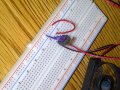
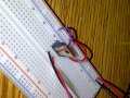
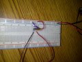
I do not have a schematic, but I have attached some more pictures. When I remove the regulator, the speed of the fan increases. So I'. guessing the regulator is functioning well. It's just my multi metre shows 2 v when I touch the wires of the fan. It is probably just a connection error. One more question, if I add more regulators in serious with the reduced voltage double? i.e two 12v fixed regulators will reduce a 12v device it to 6v?
 

Audioguru

Joined Dec 20, 2007
11,248
Where are your "attached" pictures?

If a 12V regulator has an input that is at least 14V then its output is 12V if the load current is 1A or less. Its output is regulated at 12V so it should not drop if it is not overloaded.

We do not know if the input voltage to your 12V regulator drops below 14V when you connect the fan. Measure it and tell us.

You should learn how to draw or copy schematics. I use Microsoft Paint program to copy and modify schematics and parts of schematics.
 

Audioguru

Joined Dec 20, 2007
11,248
How do I know which ends on the capacitors to connect to the regulator?
Ceramic and film capacitors are not polarized. Use ceramic capacitors at the regulator.
Electrolytic capacitors have a black bar on the case beside the negative wire (many years ago the case was marked with a + beside the positive wire).
 

Audioguru

Joined Dec 20, 2007
11,248
I have never seen a 0.33uF or 0.1uF electrolytic capacitor.

An electrolytic capacitor is used for low audio frequencies or to filter rectified mains (120Hz) with a value more than 2.2uF up to thousands of uF.
A ceramic capacitor is good for filtering away high frequencies where a regulator might oscillate.
A film capacitor is good for coupling audio and is good up to medium frequencies.
 

Thread Starter

droggie

Joined Oct 21, 2012
137
I have some .01 and 1uf ceramic capacitors. Can I use them or another variable? Because I do not have any .03 capacitors. And when connecting the capacitor to the voltage regulator do I connect one end to the input and the other end to the output? And finally, should I connect anything to the ground of the regulator? If so, where?
 

Audioguru

Joined Dec 20, 2007
11,248
I have some .01 and 1uf ceramic capacitors. Can I use them or another variable?
0.01uF is too small. The 1uF ceramic capacitor will be fine for the input or output (or both) capacitor.

I do not have any .03 capacitors.
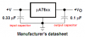
Nobody said to use 0.03uF. The datasheet and I say the input capacitor should be a 0.33uF ceramic capacitor. They are cheap and common. Buy one and use it.

And when connecting the capacitor to the voltage regulator do I connect one end to the input and the other end to the output?
No.
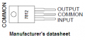
In my post #11 I copied the schematic from the datasheet. It shows the center pin (common) of the regulator connected to ground and the input and output capacitors also connected to ground. There is no capacitor connected from input to output.

And finally, should I connect anything to the ground of the regulator? If so, where?
The datasheet of the regulator shows a sketch of which pin is which. The schematic I copied from the datasheet in my post #11 shows the center pin (common) connected to ground. The input and output capacitors are connected to the common pin. The input ground and output ground are also connected to the common pin.
 

Attachments

Audioguru

Joined Dec 20, 2007
11,248
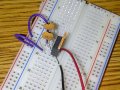
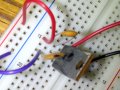
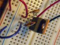
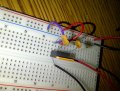
The output capacitor marked "101" is only 0.0001uF (100pF) which is much too small.
I cannot see the marking on the input capacitor.
BOTH CAPACITORS ARE NOT CONNECTED TO GROUND, instead each capacitor is shorted.

The center pin of the regulator is its ground pin but you have it connected to nothing.

What is the black wire?
What is the red wire?
 
Top