Facebook
 Google
 GitHub
 Linkedin
I found a external power supply that I can purchase from digikey. But the only one I could find with the least amount of power was a 10W 5v 2A power supply. The one that is used on the Explorer 16 development board from which I am using the schematics from has a 9v 0.75A power supply.
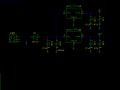
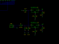
I am curious what modifications I need to make to the schematic diagram to make this work. I have attached the schematic diagram that was given to me for the explorer 16 development board. I have looked up the spec sheet for the LM1117 Voltage Regulator. It says that the max current that it can handle is 1500mA and it is rated for 800mA. Do I need to add a resistor before the LM1117 so that I do not exceed the max rated current.
The specs also mention that it is important that I use 10uF Tantalum Capacitors. before and after the LM1117. How is the performance effected by using one Ceramic 0.1uF and one 47uF Tantalum Capacitor on both sides.
Any replies would be much appreciate.")
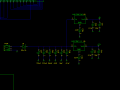
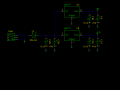
I am curious what modifications I need to make to the schematic diagram to make this work. I have attached the schematic diagram that was given to me for the explorer 16 development board. I have looked up the spec sheet for the LM1117 Voltage Regulator. It says that the max current that it can handle is 1500mA and it is rated for 800mA. Do I need to add a resistor before the LM1117 so that I do not exceed the max rated current.
The specs also mention that it is important that I use 10uF Tantalum Capacitors. before and after the LM1117. How is the performance effected by using one Ceramic 0.1uF and one 47uF Tantalum Capacitor on both sides.
Any replies would be much appreciate.
Attachments
-
 6.3 KB Views: 80