 Facebook
 Google
 GitHub
 Linkedin
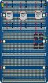
First off, let me clarify that my experience is somewhere in between Beginner and Primate. This is my first adventure into building my own IC and Im sure that my post will be full of wrong assumptions and misused terms. Go gentle on me. That being said, Im currently in the early stage of designing a customized Power Distibution and Control board for LEDs because no one seems to make what I want. It is full of hodge podge parts that are meant for other uses, or wont do what I think theyll do at all. Any suggestions or pointers outside the scope of my question are definitely welcome. Especially in regards to the power system and voltage regulation. At any rate, I have a question about Power regulation within the circuit. Ive included my two preliminary renderings Im working on, the primary circuit diagram however only shows the power system so far, not the components behind it. havent gotten that far yet. The power will come from two NiMH batteries in parallel rated, theoretical, at 7.2V/4400mAh.. All of which is going to be delivered to the circuit components through 3 UBEC Step down chips to get the voltage to the appropriate level for the components and lights. The UBECs regulate power to 5V/3A. Each UBEC is intended to account for one of the three seperate "systems" I plan to build. My question is this:
1. At least one component will draw constant power of 5V/ 2,5A with occasional, momentary surges of up to 4A which is well under the UBECs supplied current. However, with the UBECs set up "In parallel" so to speak, and all rejoining into a single circuit before being diverted back out to each individual system Im going to build, when the current surges above the individual UBECs current limit, will the component be able to meet its current demand by pulling the additional current through another UBEC? For example, Component A surges to 4A, to meet the demand, 3A channels through UBEC 1 and an additionjal 1A is drawn through UBEC 2? and all components.
2. Considering the pathways that the UBECS are channeled and then all supplied power being repooled before being applied, what will be the theoretical levels of power downstream of the UBECs? Does power/.amperage follow the same rules as batteries when being wired in series or parallel? Or is it stable at the levels set by the UBEC?
3.. Do I have to return the ground for each circuit to the UBEC after application in the circuit? Or am I able to ground the end of each circuit to one of the downstream ground circuits? And if I can, when the back end of the circuit is grounded to the circuit ground pathway, will it naturally reroute back to the UBEC even if the pathway is shunted directly back to the battery negative? Or will it bypass the UBEC ground path and "head on home" to the battery negative itself, if the pathway is open to do so?
Im also him-hawing with switching the power supply over to 4 3.7V 3500mAh cell phone batteries in series to get the circuit up to 12V to make possible using a few different components. As id still be using 5V components and using the UBECs, Im curious, what happens to all the scrubbed off voltage in that scenario? Any opinions and suggestions in general about the batteries, power distribution, configuration, UBECs, or breadboard power supply circuts would be greatly appreciated. Seriously, take me to school. Thanks!
Tim
Attachments
-
 1.3 MB Views: 6
 -
 3.1 MB Views: 6


