Voltage Reference vs Power supply voltage help

MrChips

Joined Oct 2, 2009
34,817
A proper voltage regulator also provides line regulation as well as load regulation.
Yes and no.

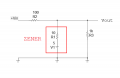
Let us take this circuit as an example.

1739739438508.png

Let us suppose,
Vs = 20 V
Vz = 10 V
Imax = 10 mA

We design for Rs,
Rs= (Vs - Vz) / Imax = ( 20V - 10V) / 10 mA = 1k Ω

If RL = 1k Ω, IL = 10 mA, VL = 10 V
Regulation occurs for varying loads so long as RL is 1k Ω or higher.
If Vs falls below 20 V, voltage regulation fails.

In order maintain the desired output of 10 V even if Vs falls below 20 V, we have to alter the design criteria.
Even though the specified Imax is 10 mA, we would have to design for a higher Imax, i.e. we would have to lower the value of Rs.
Then you have to increase the wattage rating of both Rs and the zener diode.

Suppose we make Rs = 500 Ω instead of the designed 1000 Ω.
Imax is now 20 mA and RL can fall as low as 500 Ω.

On the input side, it means that Vs can now fall to 15 V and still maintain output regulation at 10 mA @ 10 V.

To summarize, yes, you can provide some degree of line and load regulation but only if you modify the design criteria.
 

BobaMosfet

Joined Jul 1, 2009
2,211
thanks crutschow...so is voltage regulator same as voltage reference ? are they the same thing ? if not what are the major differences between the two ?
Let's clarify your terms: "Voltage Regulator" It regulates voltage to a specific level. "Voltage Reference" This is a regulated voltage level that does not change that you can compare against with an Op-Amp or other means to ensure your 'staying' calibrated. This is how electronic test sets are calibrated.
 

DC_Kid

Joined Feb 25, 2008
1,242
Voltage Regulator vs Voltage Reference
What is the difference?
There is no difference. Any difference is in the application.
When reference is in an IC package, it is usually way more stable/precise/accurate than an IC that is used for power ("regulator").

In my experience, references are for "very high" impedance loads/input/stage, the voltage is a reference with little to no "power".

Below is the LTspice sim showing the difference in a 5V Zener voltage change
Can you sim a TLE2425 with Vin 4-40v with 1k and 5k loads.
 
Last edited:

MrAl

Joined Jun 17, 2014
13,707
team,

Hope you all are well. I'm graduated as electrical engineer back 2013 and never worked as electrical engineer ever since due to lacking of opportunities at least where I live. So, now am trying to refresh my memory about my back ground so am watching you tube channels and stuff like that. And at the moment am reviewing all electronics components and stuff and I cam cross diodes.

So my question is that Zener diode can be used as a reference voltage does that mean it can serve as another power supply voltage for a circuit ? so more voltage in the circuit ? also i read that it can be used or function as a voltage regulator does that means that it will generate stable voltage irrespectively of other i.e resistors or load in circuit ? Thanks in advance team.
Hi,

Most of the previous posts addressed some of the issues already so I'll just add a little that will hopefully give you some insight as to how zener diodes work.

Since you had engineering courses already you must know what a component 'model' is right? I hope so, but I'll still briefly outline the idea behind a circuit component model.

A model is a circuit with several components in it that is designed to mimic a particular component that has more characteristics than just a single component like a resistor or capacitor. For example, a model of a more real life capacitor may be made from an ideal capacitor and a parallel resistor, alone with a series resistor. These three components create a model of a capacitor that is more like a real life capacitor even though it is not perfect. We can make it even better by adding a little series inductance, but sometimes we don't need it to be that accurate especially when we just want to know how a basic capacitor works.

Now turning to the zener diode, we can model this in it's most basic form, as a battery in series with a resistor. Yes, that might sound strange, because a battery produces power but a zener diode does not. The catch is, this model is only used when the zener is FORWARD biased. When it is reverse biased, the zener is considered to be an open circuit. That means that the model can switch its topology depending on what the external conditions are in the circuit such as voltage across the zener.
The end result of this is that when the zener is biased normally (such as used to help to regulate a voltage) the battery absorbs energy just like a zener diode, and the series resistor gives it a 'soft' clamping action. You can imagine what would happen if we just modeled it as a battery, it would keep the voltage perfectly constant, but that's not what a zener does because it cannot do that because of the way it is made. As the external voltage rises, the battery absorbs more and more energy and the voltage across the modeled zener rises, but it does not rise as much as it would if the zener was not there at all because there is now current flow through the series resistor and battery and with some external resistance in series with that zener it clamps the voltage to a certain range depending on the external resistance.

So what does this look like when we try to use it as a voltage regulator. It looks like the voltage still rises, but with the external resistance in series with the internal resistance and internal 'battery' of the zener, it does not rise as much. It's like a voltage divider with a minimum voltage. If the zener is say a 5 volt zener, it will keep the voltage somewhat close to 5v provided there is an external series resistance. It is not perfect by any means though, because of the series resistance in the model. To get a more perfect regulation we use a different device we call a voltage reference diode, or just a voltage reference chip, or an actual voltage regulator IC chip.

In the attachment you can see the zener model enclosed within the red rectangle. If you analyze this circuit, you will see that Vout changes somewhat as Vin varies from say 10v to 20v. If you remove the zener, Vout will change much more ad Vin varies from 10v to 20v. With the zener in place the output still varies, but not as much as without the zener diode.
Remember though that if the input goes below 5v, the zener no longer conducts and becomes an open circuit. You must make that change in topology before you analyze it again. With just 4v input, the zener is open circuit, and so we are left with just a resistive voltage divider with R1 and R3 and clearly that does not make a regulator of any kind.

BTW, the 'model' used here is what we call a behavioral model because it models the behavior of a zener. A physical model models the physics of the zener but will be more complicated to analyze and understand. The basic operation of both will be about the same though with the physical model being more accurate that's all.
 

Attachments

Thread Starter

shakmana

Joined Feb 15, 2025
11
Hi,

Most of the previous posts addressed some of the issues already so I'll just add a little that will hopefully give you some insight as to how zener diodes work.

Since you had engineering courses already you must know what a component 'model' is right? I hope so, but I'll still briefly outline the idea behind a circuit component model.

A model is a circuit with several components in it that is designed to mimic a particular component that has more characteristics than just a single component like a resistor or capacitor. For example, a model of a more real life capacitor may be made from an ideal capacitor and a parallel resistor, alone with a series resistor. These three components create a model of a capacitor that is more like a real life capacitor even though it is not perfect. We can make it even better by adding a little series inductance, but sometimes we don't need it to be that accurate especially when we just want to know how a basic capacitor works.

Now turning to the zener diode, we can model this in it's most basic form, as a battery in series with a resistor. Yes, that might sound strange, because a battery produces power but a zener diode does not. The catch is, this model is only used when the zener is FORWARD biased. When it is reverse biased, the zener is considered to be an open circuit. That means that the model can switch its topology depending on what the external conditions are in the circuit such as voltage across the zener.
The end result of this is that when the zener is biased normally (such as used to help to regulate a voltage) the battery absorbs energy just like a zener diode, and the series resistor gives it a 'soft' clamping action. You can imagine what would happen if we just modeled it as a battery, it would keep the voltage perfectly constant, but that's not what a zener does because it cannot do that because of the way it is made. As the external voltage rises, the battery absorbs more and more energy and the voltage across the modeled zener rises, but it does not rise as much as it would if the zener was not there at all because there is now current flow through the series resistor and battery and with some external resistance in series with that zener it clamps the voltage to a certain range depending on the external resistance.

So what does this look like when we try to use it as a voltage regulator. It looks like the voltage still rises, but with the external resistance in series with the internal resistance and internal 'battery' of the zener, it does not rise as much. It's like a voltage divider with a minimum voltage. If the zener is say a 5 volt zener, it will keep the voltage somewhat close to 5v provided there is an external series resistance. It is not perfect by any means though, because of the series resistance in the model. To get a more perfect regulation we use a different device we call a voltage reference diode, or just a voltage reference chip, or an actual voltage regulator IC chip.

In the attachment you can see the zener model enclosed within the red rectangle. If you analyze this circuit, you will see that Vout changes somewhat as Vin varies from say 10v to 20v. If you remove the zener, Vout will change much more ad Vin varies from 10v to 20v. With the zener in place the output still varies, but not as much as without the zener diode.
Remember though that if the input goes below 5v, the zener no longer conducts and becomes an open circuit. You must make that change in topology before you analyze it again. With just 4v input, the zener is open circuit, and so we are left with just a resistive voltage divider with R1 and R3 and clearly that does not make a regulator of any kind.

BTW, the 'model' used here is what we call a behavioral model because it models the behavior of a zener. A physical model models the physics of the zener but will be more complicated to analyze and understand. The basic operation of both will be about the same though with the physical model being more accurate that's all.
Thank you sooo much MrAI for such detailed explanation made so much sense !!! if I would ask you please, from where I should start refreshing my memory about electrical engineering I mean starting from what courses or topics as a guy who hasn't practiced or used his knowledge or studies in electrical engineering for 10 years .....
 

MrAl

Joined Jun 17, 2014
13,707
Thank you sooo much MrAI for such detailed explanation made so much sense !!! if I would ask you please, from where I should start refreshing my memory about electrical engineering I mean starting from what courses or topics as a guy who hasn't practiced or used his knowledge or studies in electrical engineering for 10 years .....
Hello again,

Well, if you have gotten rusty on your circuit analysis techniques I would say start from there. Refresh your analysis techniques because that is what allows you to understand circuits that you are not familiar with yet. This might seem dry and useless at first, but it's a key point when it comes to understanding a circuit in electronics. You can back that up with some hands on experience by starting a small personal "lab" where you have some resistors, capacitors, etc., and do some little circuits. Compare your math analysis to the measured results. Also, a simulator is great for this if you don't want to buy electronic parts or even if you do. You can verify your analysis with a simulation, and verify a simulation with your analysis and real life measurements of real life circuits.
I don't know how much cash you want to invest in this, but an oscilloscope is a good idea if you intend to work on real life circuits, even a cheaper model can get you pretty far. You can find scopes around $100 USD or so or maybe $150 that are good enough for study, and you can even get one for under about $30 USD if you restrict the scope of your study to mostly audio circuits, which can show us a lot about AC circuits.

As I am sure you know, math is the basis for all analysis so the more math you have the better. Refresh some of your math skills like at least algebra, which can get you pretty far, and then trig and calculus with some geometry.
Algebraic simultaneous equations are a must, and can get you going pretty far.

I don't really know what you have already done in the past so it's hard to recommend anything in particular. If you can provide a little more background maybe I can help a little more, or maybe you can even help me :)
 

MrAl

Joined Jun 17, 2014
13,707
Here's the spice model for the TLE2425 for what it's worth.

Code:
* TLE2425 OPERATIONAL AMPLIFIER “MACROMODEL” SUBCIRCUIT
* CREATED USING PARTS RELEASE 4.03 ON 08/21/90 AT 13:51
* REV (N/A) SUPPLY VOLTAGE: 5 V
* CONNECTIONS: INPUT
* | COMMON
* | | OUTPUT
* |||
.SUBCKT TLE2425 3 4 5
*
* OPAMP SECTION
C1 11 12 21.66E-12
C2 6 7 30.00E-12
C3 87 0 10.64E-9
CPSR 85 86 15.9E-9
DCM+ 81 82 DX
DCM- 83 81 DX
DC 5 53 DX
DE 54 5 DX
DLN 92 90 DX
DLP 90 91 DX
DP 4 3 DX
ECMR 84 99 (2,99) 1
EGND 99 0 POLY(2) (3,0) (4,0) 0 .5 .5
EPSR 85 0 POLY(1) (3,4) -16.22E-6 3.24E-6
ENSE 89 2 POLY(1) (88,0) 120E-6 1
FB 7 99 POLY(6) VB VC VE VLP VLN VPSR O 74.8E6 -10E6 10E6 10E6
+ -10E6 74E6
GA 6 0 11 12 320.4E-6
GCM 0 6 10 99 1.013E-9
GPSR 85 86 (85,86) 100E-6
GRC1 4 11 (4,11) 3.204E-4
GRC2 4 12 (4,12) 3.204E-4
GRE1 13 10 (13,10) 1.038E-3
GRE2 14 10 (14,10) 1.038E-3
HLIM 90 0 VLIM 1K
HCMR 80 1 POLY(2) VCM+ VCM- 0 1E2 1E2
IRP 3 4 146E-6
IEE 3 10 DC 24.05E-6
IIO 2 0 .2E-9
I1 88 0 1E-21
Q1 11 89 13 QX
Q2 12 80 14 QX
R2 6 9 100.0E3
RCM 84 81 1K
REE 10 99 8.316E6
RN1 87 0 2.55E8
RN2 87 88 11.67E3
RO1 8 5 63
RO2 7 99 62
VCM+ 82 99 1.0
VCM- 83 99 -2.3
VB 9 0 DC 0
VC 3 53 DC 1.400
VE 54 4 DC 1.400
VLIM 7 8 DC 0
VLP 91 0 DC 30
VLN 0 92 DC 30
VPSR 0 86 DC 0
 RFB 5 2 1K
RIN 30 1 1K
RCOM 34 4 .1
*REGULATOR SECTION
RG1 30 0 20MEG
RG2 30 31 .2
RG3 31 35 400K
RG4 35 34 411K
RG5 31 36 25MEG
HREG 31 32 POLY(2) VPSET VNSET 0 1E2 1E2
VREG 32 33 DC 0V
EREG 33 34 POLY(1) (36,34) 1.23 1
VADJ 36 34 1.27V
HPSET 37 0 VREG 1.030E3
VPSET 38 0 DC 20V
HNSET 39 0 VREG 6.11E5
VNSET 40 0 DC -20V
DSUB 4 34 DX
DPOS 37 38 DX
DNNEG 40 39 DX
.MODEL DX D(IS=800.0E-18)
.MODEL QX PNP(IS=800.0E-18 BF=480)
.ENDS
 

Thread Starter

shakmana

Joined Feb 15, 2025
11
Hello again,

Well, if you have gotten rusty on your circuit analysis techniques I would say start from there. Refresh your analysis techniques because that is what allows you to understand circuits that you are not familiar with yet. This might seem dry and useless at first, but it's a key point when it comes to understanding a circuit in electronics. You can back that up with some hands on experience by starting a small personal "lab" where you have some resistors, capacitors, etc., and do some little circuits. Compare your math analysis to the measured results. Also, a simulator is great for this if you don't want to buy electronic parts or even if you do. You can verify your analysis with a simulation, and verify a simulation with your analysis and real life measurements of real life circuits.
I don't know how much cash you want to invest in this, but an oscilloscope is a good idea if you intend to work on real life circuits, even a cheaper model can get you pretty far. You can find scopes around $100 USD or so or maybe $150 that are good enough for study, and you can even get one for under about $30 USD if you restrict the scope of your study to mostly audio circuits, which can show us a lot about AC circuits.

As I am sure you know, math is the basis for all analysis so the more math you have the better. Refresh some of your math skills like at least algebra, which can get you pretty far, and then trig and calculus with some geometry.
Algebraic simultaneous equations are a must, and can get you going pretty far.

I don't really know what you have already done in the past so it's hard to recommend anything in particular. If you can provide a little more background maybe I can help a little more, or maybe you can even help me :)
Thanks again MrAI, I think for the time being I would go with simulator am not sure what you guys are using LTspice that's as far as I remember if my memory doesn't fail me. I have done many courses in the university a piece of everything I mean I didn't have a major field within my electrical engineering study due to the unavailability of all courses. So I had circuit courses 1 to 3, liner system course, intro to engineering electromagnetic, microelectronics, digital design, control system, communication system and operational amplifier system design. Math of course as you said my friend I need also to refresh my memory, I had calculus from 1 to 3 physics as well. It's just that I want to start slow and little simple then gradually get more deep or harder. I know I can find sort of roadmaps of learning or study but I would rather hear from someone.
 

MrAl

Joined Jun 17, 2014
13,707
Thanks for that info, but as I noted, I need motivation to put that model into LTspice, and so far, that hasn't happened. :)
Yeah :)
What I found strange is that the data sheet does not seem to show an "internal" diagram like most data sheets do. Even a behavioral diagram would be good enough for me, with maybe the output stage being shown in more detail. I wanted to know how they drive the output without going though an entire section of the spice model. I did see they only use NPN transistors which struck me as a little strange. I would have thought an NPN and a PNP for the output stage to handle both source and sink currents. I'm not too motivated to go through the whole model and figure it out either :)
Maybe in the future.
It also struck me as strange that the spice model was so huge. Such a simple function. Maybe we should be thankful though it may show a lot of unusual behaviors we would not see with just an op amp and PNP and NPN output stage, or as they seem to be using, the two NPN output stage.
 
Last edited:

MrAl

Joined Jun 17, 2014
13,707
Thanks again MrAI, I think for the time being I would go with simulator am not sure what you guys are using LTspice that's as far as I remember if my memory doesn't fail me. I have done many courses in the university a piece of everything I mean I didn't have a major field within my electrical engineering study due to the unavailability of all courses. So I had circuit courses 1 to 3, liner system course, intro to engineering electromagnetic, microelectronics, digital design, control system, communication system and operational amplifier system design. Math of course as you said my friend I need also to refresh my memory, I had calculus from 1 to 3 physics as well. It's just that I want to start slow and little simple then gradually get more deep or harder. I know I can find sort of roadmaps of learning or study but I would rather hear from someone.
Hello again,

I always like to see people that are interested in this stuff because I've delt with it almost my entire life.
One thing I see as important in electronics is circuit analysis using at least one method that you know well, like Nodal Analysis. If you learn that (if you don't know that already that is) you can get to understand a lot of different circuits. Even if it is just for DC circuits to start, with just resistors and a battery or two and maybe a current source. Then move on to dependent sources. From there you can get into AC circuits pretty quickly if you already understand basic complex arithmetic, and of course algebra with simultaneous equations or matrix math.
Circuit analysis is like its own little world and circuit analysis is what opens it up for understanding. And yeah, simulators are invaluable these days too. Most people here use the LT Spice simulator I think they call it (or called it) SwitcherCad. That allows us to share circuits and verify analyses.

As far as components go, constant voltage sources (like batteries) and resistors are easiest to understand. Then there is the constant current source which is next up. If you can understand these circuit thoroughly, you can move to the more complicated stuff a lot easier.

Again, I do not know exactly what you know or did in the past so I'm mentioning what I can think of at the moment. You probably already know some or even a lot of this stuff already.
 

DC_Kid

Joined Feb 25, 2008
1,242
I don't have the model installed for it.
I need to be motived to do that, which is a little tedious to do with LTspice.
Why is that "Virtual Ground" component of particular interest?
Only because its' specs seem nice, wide input range with very stable output with low drift from temps. It's more of "reference" item, although is does have decent mA rating.
 

MrAl

Joined Jun 17, 2014
13,707
Only because its' specs seem nice, wide input range with very stable output with low drift from temps. It's more of "reference" item, although is does have decent mA rating.
Hi,

Yeah from what I read so far, and that's probably the end of it for me for now, is that it is a 'precision' power supply splitter which would, I gather, be of use in ADC systems where single bit stability is important. That, I suppose, would be better than using a general purpose op amp for the same type of circuit.
 

kiroma

Joined Apr 30, 2014
80
Hi Kiroma...what exactly you mean by voltage reference? could you explain further please? when you say that zener diode can be used as a power supply for some circuit does this mean it can work as a power supply itself without external power supply ?
Sorry for the delayed response, didn't see the notifications.
Voltage reference in electronics is meant to be a voltage that is stable to some degree.
It doesn't mean it will generate power out of nothing, it has to be powered from electricity, be it the mains, a battery, a super capacitor that's charged, a photovoltaic cell etc.
So the "it can be used as a power supply" means that it has a relatively good stable voltage that can be used to connect other circuits that require stable voltage.
 

crutschow

Joined Mar 14, 2008
38,513
Basic definitions:
  • Power Supply -- Generates a stable voltage with sufficient output current to power circuits/equipment.
  • Voltage Reference -- Generates a stable voltage (typically more stable than a power supply), with a low output current (typically no more than a few 10's of mA) where a stable/accurate voltage reference is required (such as for A/D converters, comparator circuits, accurate power supply, etc.).
Both of those do not intrinsically generate power, they require some sort of power source for their operation (battery, AC rectified DC, etc.).
 
Last edited:

BobaMosfet

Joined Jul 1, 2009
2,211
When reference is in an IC package, it is usually way more stable/precise/accurate than an IC that is used for power ("regulator").

In my experience, references are for "very high" impedance loads/input/stage, the voltage is a reference with little to no "power".


Can you sim a TLE2425 with Vin 4-40v with 1k and 5k loads.
No, a reference voltage is exactly that - a REFERENCE to be compared against. Impedance is a matter of "stiff" versus "weak" signal based on amount of current in the signal. How much current the reference signal has is a matter of choice of whomever designed the circuit and the constraints they engineer under. You use current to overcome noise. When we discuss impedance, we are talking about reactance (or inductance depending). Either case is a fancy word for 'resistance' to the flow of current by means of an electrical or magnetic field instead of friction (like a resistor).

This is why in audio equipment you usually want output from one device (like a phonograph) to have enough current (low-impedance) to drive the signal far enough, strong enough, and you have a matching impedance on the input side (speaker) so that you do not have ringing in the signal.

Ops Amps are an example of infinite impedance on their input, because they aren't interested in current, they want a discrete input signal solely for comparison. The output side of the OpAmp however, is a current driver, and can drive the output signal with a low-impedance.
 
Top