 Facebook
 Google
 GitHub
 Linkedin
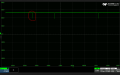
I'm working on a power interrupt test using RM1D500D10. The goal is to create a short power interruption with a control signal. However, when testing without a load, I'm encountering an issue where the voltage doesn't drop to 0V
I specifically chose this part because it doesn't have any internal capacitors at the output. The load itself does have some capacitors to prevent power interruption. Therefore, ideally, I don't want to connect the load until I confirm that the power interrupt test circuit is working as intended.
Any suggestions on how to address this voltage drop issue would be greatly appreciated. Thanks in advance for your help!
Below are 2 captures from the Datasheet


Control Signals:
I specifically chose this part because it doesn't have any internal capacitors at the output. The load itself does have some capacitors to prevent power interruption. Therefore, ideally, I don't want to connect the load until I confirm that the power interrupt test circuit is working as intended.
Any suggestions on how to address this voltage drop issue would be greatly appreciated. Thanks in advance for your help!
Below are 2 captures from the Datasheet
Control Signals:
- Pin#3: 15VDC, with an interrupt of 40ms
- Pin#4: GND
- Pint#1: 270VDC
- Pin#2: No load, tied directly to CH4 - Differential Probe of Oscilloscope for testing.
Attachments
-
 144.8 KB Views: 11
Last edited:


