Voltage drop issue during load switching with AP2301B at low battery voltage

Thread Starter

prashant.bdri

Joined May 15, 2025
4
1
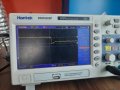
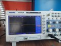
I’m using two AP2301B MOSFETs in a back-to-back config to switch between battery (BATT+) and USB 5V. The gate is controlled via a 100k pull-up and 100k to GND.
Attached: Oscilloscope capture
signal-2025-05-15-42036 PM.jpeg


Schematic
Screenshot 2025-05-15 170023.png

Issue: When battery voltage is around 3.7V, I see a voltage dip (~2.2V drop) on VCC during switching. This resets my MCU. But when battery voltage is above 4V, the dip is gone or negligible.

Questions:

Why does the drop only happen at lower battery voltages?

Is it due to MOSFET body diode or slow gate transition?

How can I make switching smoother and prevent MCU reset?
 

dendad

Joined Feb 20, 2016
4,634
If you are going to remove a FET, I would thing Q6 is the one to go. Otherwise, with Q5 gone, the +5V will feed the battery via the Q6 body diode.
 

spenkmo

Joined Apr 24, 2025
25
These are enhancement-mode MOSFETs. They are turned on when G is applied a negative bias wrt S. The current flows from S to D. Q6 is on when +5V supply becomes 0v, as its G is negatively biased wrt S. For Q5, mainly the internal diode passes the current, which explains the drop of the output voltage.
 

Thread Starter

prashant.bdri

Joined May 15, 2025
4
These are enhancement-mode MOSFETs. They are turned on when G is applied a negative bias wrt S. The current flows from S to D. Q6 is on when +5V supply becomes 0v, as its G is negatively biased wrt S. For Q5, mainly the internal diode passes the current, which explains the drop of the output voltage.
If you are going to remove a FET, I would thing Q6 is the one to go. Otherwise, with Q5 gone, the +5V will feed the battery via the Q6 body diode.
These are enhancement-mode MOSFETs. They are turned on when G is applied a negative bias wrt S. The current flows from S to D. Q6 is on when +5V supply becomes 0v, as its G is negatively biased wrt S. For Q5, mainly the internal diode passes the current, which explains the drop of the output voltage.
i tried removing both the q5 and q6 ,

the result i found:
when i removed the q6 it worked without being reset but the switching time is much higher.

and when i removed the q5 it wont ,the mpu gets reset again the same problem.
 

Attachments

Thread Starter

prashant.bdri

Joined May 15, 2025
4
If you are going to remove a FET, I would thing Q6 is the one to go. Otherwise, with Q5 gone, the +5V will feed the battery via the Q6 body diode.
i tried removing both the q5 and q6 ,

the result i found:
when i removed the q6 it worked without being reset but the switching time is much higher.

and when i removed the q5 it wont ,the mpu gets reset again the same problem.
 
Top