Facebook
 Google
 GitHub
 Linkedin

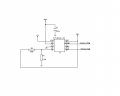
I have a problem using the PFI/PFO# function of the TPS3619-33. My schematic is shown here attached. This is part of a bigger schematic, all constructed on the same PCB.
The R1/R2 resistors are intended to set a sensing threshold so that when the VBAT voltage falls below around 2.6V, the PFO# output goes to LOW. However, although the battery is around 3.3, PFO# is not HIGH but LOW. When I measured the output voltage of the divider, I found it to be 0.7V. I have removed the R1 resistor (it is indeed 570k, no error in this) and the resistance between VBAT and the PFI pin is found to be around 660k.
Well, something very weird is happening here... Do you think is it something to do with the TPS3619-33 or some bug of the PCB?
Nikos
EDIT : I forgot to mention that although VBAT is intended to be the voltage from a Li-ion battery, the above behaviour is seen even with an input voltage from a power supply and even without any voltages on the PCB, the values of the resistors R1 and R2 are not their expected.
The R1/R2 resistors are intended to set a sensing threshold so that when the VBAT voltage falls below around 2.6V, the PFO# output goes to LOW. However, although the battery is around 3.3, PFO# is not HIGH but LOW. When I measured the output voltage of the divider, I found it to be 0.7V. I have removed the R1 resistor (it is indeed 570k, no error in this) and the resistance between VBAT and the PFI pin is found to be around 660k.
Well, something very weird is happening here... Do you think is it something to do with the TPS3619-33 or some bug of the PCB?
Nikos
EDIT : I forgot to mention that although VBAT is intended to be the voltage from a Li-ion battery, the above behaviour is seen even with an input voltage from a power supply and even without any voltages on the PCB, the values of the resistors R1 and R2 are not their expected.
Attachments
-
 13 KB Views: 34
Last edited: