 Facebook
 Google
 GitHub
 Linkedin
Hello,
I've got an old chart recorder that uses a pen to create curves on paper, akin to a seismograph. A solid sample is placed in a flame, and the distortion is measured by the displacement of pin that corresponds to a certain voltage. This voltage is measurable by voltmeter on two pins of the machine. The range of this system is -16VDC for the lowest level of distortion up to 16VDC for the highest possible distortion.
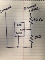
My goal is to connect an Arduino to the system so I can take the data and dump it into excel. My plan is to create a voltage divider and scale down the voltage to the 0-5V tolerance of the arduino. I've included my plan in the attached photo below. My understanding is that the arduino and the machine will need to share a GND connection, however when I'm join the grounds of the Arduino and machine together, the reading on the arduino goes to 0, and the reading by voltmeter goes to 56mV. I'm not sure what I'm doing wrong, am I missing something obvious in this scenario?
Thank you
I've got an old chart recorder that uses a pen to create curves on paper, akin to a seismograph. A solid sample is placed in a flame, and the distortion is measured by the displacement of pin that corresponds to a certain voltage. This voltage is measurable by voltmeter on two pins of the machine. The range of this system is -16VDC for the lowest level of distortion up to 16VDC for the highest possible distortion.
My goal is to connect an Arduino to the system so I can take the data and dump it into excel. My plan is to create a voltage divider and scale down the voltage to the 0-5V tolerance of the arduino. I've included my plan in the attached photo below. My understanding is that the arduino and the machine will need to share a GND connection, however when I'm join the grounds of the Arduino and machine together, the reading on the arduino goes to 0, and the reading by voltmeter goes to 56mV. I'm not sure what I'm doing wrong, am I missing something obvious in this scenario?
Thank you
Attachments
-
 95.4 KB Views: 12


