 Facebook
 Google
 GitHub
 Linkedin
Hi I am using an MCP112 "precision voltage detector" as over discharge protection on a battery pack, my setup is as follows:
Battery is connected to MCP112; when voltage is above 4.4, the output pin is driven high which enables a MOSFET to supply power to breadboard rails allowing as many as desired loads. The circuit has been running for 2 days without apparent issues..
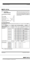
My question is: MCP112 datasheet specifies an input current (Vdd) of 10mA (absolute max rating), as well as an operating current (Idd) of 1.75uA max (listed under electrical characteristics)
Do the internal components disallow input current above 1.75uA? If so why am I given a max rating of 10mA?
What is the difference between Vdd and Idd as they relate to the datasheet?
Must I regulate the input current? If so how do I without affecting voltage because after all this is a precision voltage detector IC.
I have included the MCP112 datasheet, thanks!

Battery is connected to MCP112; when voltage is above 4.4, the output pin is driven high which enables a MOSFET to supply power to breadboard rails allowing as many as desired loads. The circuit has been running for 2 days without apparent issues..
My question is: MCP112 datasheet specifies an input current (Vdd) of 10mA (absolute max rating), as well as an operating current (Idd) of 1.75uA max (listed under electrical characteristics)
Do the internal components disallow input current above 1.75uA? If so why am I given a max rating of 10mA?
What is the difference between Vdd and Idd as they relate to the datasheet?
Must I regulate the input current? If so how do I without affecting voltage because after all this is a precision voltage detector IC.
I have included the MCP112 datasheet, thanks!
Attachments
-
 169.7 KB Views: 3


