 Facebook
 Google
 GitHub
 Linkedin
Hallo,
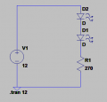
I have made a simple LED circuit with two leds in series and a resistor to limit the current. What would be the voltage at Anode of D2? 12V or 6-7V ? simulation shows 12V but actually I got 6-7V? what could be the reason?
Thanks,
Regards,
Surjit
I have made a simple LED circuit with two leds in series and a resistor to limit the current. What would be the voltage at Anode of D2? 12V or 6-7V ? simulation shows 12V but actually I got 6-7V? what could be the reason?
Thanks,
Regards,
Surjit
Attachments
-
 4.2 KB Views: 30


