 Facebook
 Google
 GitHub
 Linkedin
Hello.
In a AC RC circuit, this is the Capacitive Reactance, as you are reading should know (if you're going to answer to this question, haha).
(1)

And this is the total impedance, given a R which is the resistance in series.
(2)

Then the rms current in this circuit can be written by Vrms/Z
And it times the Xc will give us the voltage across the capacitor, as follows:
(3)

Until here I know it's all true, and I don't have any doubts about it.
But I did want to integrate an half period of the sinusoidal current to see if the voltage is equal as calculated before.
(4)

Integrating the currrent (Vrms/Z) will give us the charge "q".
By the definition of capacitance, we have that: V=q/C
That's why I put a divided by C.
Ah, omega = 2*pi*f
The integral I showed before (4) is not the voltage across the capacitor. It's simply exactly the double voltage.
Which means it should be divided by 2 before, to give us the Vc.
Solving the integral (4) give us
(5)

This is what I showed you in (4).
Multiplying by 1/2 will give us exaclty the equation number (3), which is the Vc.
Here comes the question
Why multiplied by 1/2?
Where does it come from?
Solution I thought hours later:
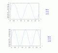
The second half of the first half period charges the capacitor with Vc.
Then it requires half of the second half period (which is negative) to discharge the capacitor, and another half of the second half period to charge negatively the capacitor.
And it goes on.
IF this is the answer, to where it goes the first half of the half period?
In a AC RC circuit, this is the Capacitive Reactance, as you are reading should know (if you're going to answer to this question, haha).
(1)
And this is the total impedance, given a R which is the resistance in series.
(2)
Then the rms current in this circuit can be written by Vrms/Z
And it times the Xc will give us the voltage across the capacitor, as follows:
(3)
Until here I know it's all true, and I don't have any doubts about it.
But I did want to integrate an half period of the sinusoidal current to see if the voltage is equal as calculated before.
(4)
Integrating the currrent (Vrms/Z) will give us the charge "q".
By the definition of capacitance, we have that: V=q/C
That's why I put a divided by C.
Ah, omega = 2*pi*f
The integral I showed before (4) is not the voltage across the capacitor. It's simply exactly the double voltage.
Which means it should be divided by 2 before, to give us the Vc.
Solving the integral (4) give us
(5)
This is what I showed you in (4).
Multiplying by 1/2 will give us exaclty the equation number (3), which is the Vc.
Here comes the question
Why multiplied by 1/2?
Where does it come from?
Solution I thought hours later:
The second half of the first half period charges the capacitor with Vc.
Then it requires half of the second half period (which is negative) to discharge the capacitor, and another half of the second half period to charge negatively the capacitor.
And it goes on.
IF this is the answer, to where it goes the first half of the half period?
Last edited:
")


