Vintage amplifier repair help needed

Thread Starter

Sonique

Joined Feb 17, 2022
23
Hi! I just signed up for the forum. I’m a beginner and I do electronics from a hobby. I'm trying to fix an old Tesla AZS 217 amplifier. Maybe you can help me with the amp problem.

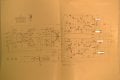
The right channel does not work on the amplifier (output transistor KD602 is defective). KC507 is also defective.

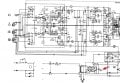
In the diagram you can see the voltages I measured before replacing the listed transistors.

Since I don't have a KD602 at the moment, I switched the correct transistor from the left channel and I replaced the KC507 with a BC547C transistor. It was supposed to be just a temporary solution and for testing purposes until I get the original transistor. When I turned on the amplifier to test it the transistor and resistor R27 smoked.

I tested all the transistors and diodes on the right channel later and they are all correct. Resistors R44 and R43 are correct. C23 instead of 500µF measures 1150µF (ESR = 0.56 Ohm) and C22 has trouble measuring. Out of 10 measurements, maybe 2 times he manages to get the value. The rest is reported by the damage part. When it manages to measure C22 = 55µF and the ESR is 2.5 Ohms.

Can anyone give me advice on where to look for a problem on the right channel of the amplifier? Can these capacitors cause the KC507 transistor to burn out?

Any help or advice would be great.
 

Attachments

Rod888

Joined Feb 14, 2022
20
do you mean the 27ohm resistor in series with c23 smoked? i dont see r27.
yes leaky capacitors can cause improper bias and be a problem. you have to take one lead off a capacitor to test it out of circuit otherwise the stray circuit resistances will botch your readings. doing a capacitance check is not so telling, what you really need to do is a leakage test. i've fixed alot of vintage stuff and cap failures are common, in fact if it was my amp i would replace ALL of the capacitors and not even bother testing them , especially electrolytics as they are most likely all leaky to some degree and only a matter of time till they fail given their age. Old radio/amplifier restoration 101 is to replace all the caps, small ceramics i wouldnt worry tooo much about but all the electrolytics and paper caps gotta go, take a good look at the ps rectifiers too while you're in there...
and current limit the supply or use a variac and ramp the power up slowly making sure bias is good, if you miss one bad component replacement in a dc coupled amp and just power it on with a bias issue you could drive all the transisors to the rail and blow every one of them in milliseconds, i speak from experience
 

AlbertHall

Joined Jun 4, 2014
12,345
If I interpret the diagram correctly the points marked 5.1V and 20.6V appear to be connected which, as they have different voltages, they cannot be.
Either something is disconnected or one of the voltages is measured incorrectly.
 

Rod888

Joined Feb 14, 2022
20
the lower channel has no bias, the transistor side of the speaker coupling caps should be 1/2 the rail voltage like the top channel so something is open somewhere, you can only really properly test transistor be jucnctions while they are in circuit other wise you have to pull them for gain and leakage tests. the hot side of the speaker should have 0v not 5 so something is leaking , maybe the speaker coupling caps but if you value your speakers NEVER run them with dc offset on them , unless you like the smell of burning voice coils this is..
you can use an 8 ohm resistor of sufficient wattage as a dummy load for testing
also if you ever work on an amp that has a transformer coupled speaker , mostly tube amps but there were a few solid state ones too, NEVER run it without a dummy load or speaker on the output, again unless you dont mind arcing and tesla coil action..
 

Thread Starter

Sonique

Joined Feb 17, 2022
23
Thanks for the answers.

@AlbertHall - I'll check everything you said.

@Rod888 - You are right, this is an R47 resistor with a value of 27 Ω.

I tested the capacitors outside the circuit.

I definitely intend to change all the electrolytes. Since the values are not standard (50µ and 500µ) should I use the first lower value or the next higher value?
Do they need to be LOW ESR or not?
 

Dodgydave

Joined Jun 22, 2012
11,284
Nearest value of Capacitors is 47uF and 470uF these should be ok as long as the voltage is the same or higher.

Clearly there's something wrong around VT12/VT13 as the output voltage is at 0V .
 
Last edited:

Rod888

Joined Feb 14, 2022
20
yes closest value lower would be just fine, old components had much looser tolerances anyway +-10% was high quality, i wouldnt worry too much about esr as all good namebrand caps will be similar, i would use high quality name brand electro's like rubicon , sprague, cornell etc
 

MrChips

Joined Oct 2, 2009
30,708
I am not a big fan of replacing capacitors.
I would normally look at voltages and circuit functionality first then decide if a capacitor needs replacing.
Measure voltages and try to resolve the bad voltages first.


Tesla AZS217.jpg

Tesla AZS217 power output.jpg
 

Rod888

Joined Feb 14, 2022
20
i suggest watching this vid

I am not a big fan of replacing capacitors.
i disagree with mr chips and so do most of vintage equipment restorers, old electrolytics are very prone to drying out and go leaky especially in older tube gear, you can look at mr carlsons lab vids on youtube about tips on restoration and he, as well as i, as well as any good restoration tech will always turf old caps, especially electrolytics!
if you dont believe me do a leakage test on the ones you have, that fact that you have dc on your speaker shows the 4x500 coupling caps are already leaking considerably and remember they are all the same vintage so the others are equally as bad or not far behind. Mr carlson lab on youtube also has a good vids on how to build your own leakage and capacitor polarity tester which will allow you to install the metalized poly caps that you refer to in the correct orientation for maximum shielding. Replace the caps, they are too old
i spent years of my life as a bench technician repairing audio and radio gear and have repaired in the thousands of units so i speak from experience, i would add defacto cap replacement is only for very aged gear, as mr chips stated this i would not do for something newer
 
Last edited:

MrChips

Joined Oct 2, 2009
30,708
You misunderstand me. Of course old aged caps go bad and need replacing.
I do not rip out all the capacitors and replace them. That is the shotgun approach. If that is your approach that is fine.
Eventually I will find the bad ones and replace them.
I have equipment over 50 years old and are still running fine with not components replaced.
 

Rod888

Joined Feb 14, 2022
20
with as few caps as that unit has shotgun approach is the way to go, as well as being faster it ensures you wont be re-visiting it in short order because you wanted to save what, $5 in parts? no sense, do it right
this is a low power amp so its not as critical but something to keep in mind is for best performance the series transistors should be matched for the best power sharing and linearity. This design isnt a complimentary push-pull but for this amp the transistor pairs vt8&9, vt10&11, and vt12&13 should be matched units. Best way to match is with a curve tracer but barring that you can do a simple better than nothing match using your transistor checker's hfe function and use transistors with the closest values you can find. This will at least balance it at dc and the lower power levels as well as increase the odds that they will track closer at the higher currents than no dc hfe match at all. If you find any of those transistors have failed i would highly recommend trying to find matched pairs. When i was in the trade i used to go down to our parts supplier and grab their whole bin of transistors and take it back to the shop and match them up on our tracer. This probably wouldn't happen today but i would be willing to bet if you went to your local supplier with your dmm hfe tester in hand they would let you go through their bin and match some up.
also if one of those transistors is bad DO NOT just replace the one thats bad. eg if vt12 is gone replace 12 and 13 both, silicon has changed alot and having a similar pair will go a long way for you.
 

Rod888

Joined Feb 14, 2022
20
also a thing to note as you are having problems with the driver transistor vt6, this is not your typical bias stabilized common emitter circuit because the emitter resistor r47 has a cap i series with it, therefore the circuit isnt using feedback for dc self- stabilization in the traditional manner , instead bias relies on the transistors and components downstream to set bias so you will obviously have to adjust your idling current, as you would after replacing anything. If you can't find bias specs for the amp you can use the working channel, measure the voltage across the collector resistor r67 which should be the same as the emitter resistor above it (i think r66, hard to read) they should be very close if everything is properly balanced. Then you can set the idling current in the repaired channel by matching that value, again if the repaired channel has equal voltages across r66 and r67 and the voltage on the transistor side of the speaker coupling caps is at 1/2 the rail voltage then you should be good to go. Dont forget your heasink compound if replacing hs mounted devices. Good luck with your project Ü
 

Thread Starter

Sonique

Joined Feb 17, 2022
23
Success !!!

I replaced all electrolytic and paper capacitors, burnt out KC507 with BC107 and output transistors KD602 with 2N3055 (paired). The quiescent current is set to 50mA.

For now, as far as I can tell, everything is working nicely. The only thing is that the Zener diode KZ714 is quite hot (the finger can stay on the heatsink for less than 1s). The diode is 10W, 28V. It is hot regardless of whether the load is present or not.

Is this perhaps a normal mode of operation?

Is it possible to replace this diode with a voltage regulator that would not heat up so much?

Due to this diode, the entire interior of the housing is slightly heated.
 

Attachments

MrChips

Joined Oct 2, 2009
30,708
Voltage after the bridge is 39V.
LM317HV will work.
LM7824 might work. It will still get warm but not as hot as the zener diode. You can mount in on a heatsink if there is room.
 

Thread Starter

Sonique

Joined Feb 17, 2022
23
On one pair of rectifier diodes the voltage is 39.4V, on the other pair it is 20V.

The voltage on the Zener diode is 28.5V.
 
Top