vibrating wire transducer for load measurment

but sir in my case there are range of capacities are given so which should i consider as a fixed.
so as excitation voltage for given load cell is 10 volt dc if the load is 1000kg then what will be my o/p
is it 200 mv?
m i right?"

and sir
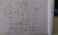
the load cell is bridge type,
u can see in pdf i have attached
 
Last edited by a moderator:

ericgibbs

Joined Jan 29, 2010
18,872
but sir in my case there are range of capacities are given so which should i consider as a fixed.
so as excitation voltage for given load cell is 10 volt dc if the load is 1000kg then what will be my o/p
is it 200 mv?
m i right?"
If the load cell is rated at 1000kG and 2mV/Vex, and Vex = 10V,, when the load cell is fully loaded at 1000kG, you will get a 20mV output

EDIT:
If the load is half, say 500kG then Vout will be 10mV
 

ericgibbs

Joined Jan 29, 2010
18,872
That circuit is what I am suggesting for amplifying your load cell signal.
If you are using a LM393 or other comparator as a 'window detector' as you stated in your earlier posts, why do you need an ADC.?

If you use a ADC how do you plan to recognise the window set points of 25/50/75%..?


sir my aim is to just track the full load by using that load cell
so from above ckt which i have copied (its urs solution)...
if i design for my application
by giving 10 v to the i/p,then i will get the 20 mv o/p for full load i.e for 1000kg,
and amplifying the o/p by means of ad623 and then drive the relay for full load
 
Last edited by a moderator:

ericgibbs

Joined Jan 29, 2010
18,872
hi nick,
That circuit would work, add a LM393 'window' comparator circuit to the output of the AD623.
Can you do that.?

Please post a PDF of the load cell.
E

EDIT:
You cannot drive a relay directly from the AD623 output, you need to add a transistor driver.
 
sir,
for 50% load i will get some fixed mv o/p
for 75% of load i will get fixed mv o/p
for 100% load i will get some fixed o/p
and
in lm 339 there are two i/p terminal for comparision i.e. reference and other i/p is from load cell so the o/p is depend upon comparision of these two

pdf for load cell

hi sir
the o/p of lm339 will be high only when i/p from load cell will cross the reference and i can drive the relay from that high and low transition of lm339...by means of 547b transistor..
m i right?
 

Attachments

Last edited by a moderator:

ericgibbs

Joined Jan 29, 2010
18,872
Got your PDF OK.
Please confirm the following.
You said earlier that you wanted set points for 25,50,75% of the load cell loading, is that still the case.?
Its important that you have a precise set point for the relay to operate at, so you need a comparator to detect the set point voltage output from the AD623, THEN operate the relay.
 
and i think o/p signal from load cell is differential

actually sir there are either cases..
i.e.
some times i want to track the o/p in intervals.
(it can be my further development)
and some times it will be only for full load..

but it will be sufficient for me if i can design circuit for full load..

img
 

Attachments

Last edited by a moderator:

ericgibbs

Joined Jan 29, 2010
18,872
Your circuit of post #67 would work OK, you need to add a diode across the relay coil.

The load cell data is usually specified for a full load value.
eg: for given choice range of L/C's of say 50kG , 100kg or 1000kG at say 2mV/Vex, then any of these load cells would give 20mV when fully load when powered by 10Vdc.

A L/C rated for only 1kG max load would still give 20mV if specified as 2mv/V

I will try to post a circuit later.
 

ericgibbs

Joined Jan 29, 2010
18,872
Look at this option, it shows a set point at 500kG and 750kG, you could add the other parts of the LM339 if required.
E
The simulation is LTSpice.
 

Attachments

thanku very much sir..
i will try u r ckt and let u knw
:)

sir can you plz send me link for to download ltspice software

sir as i m at the entry level
i dont understand that how do we calculate the values for resistance capacitor,
again how we decide the which transistor will suitable for the circuit ,
why 2n222 why not bc547,
means i knw that there ratings are differernt on which we r using them...
but i want to knw how exactly the component selection are done//..
is there any pdf if u having plz share with me.
and how do u calculate resistor and capacoitor values in this load cell signal conditioning ckt

k sir bye bye..
c u 2maro
 
Last edited by a moderator:

ericgibbs

Joined Jan 29, 2010
18,872
sir can you plz send me link for to download ltspice software
Download the free program.
http://www.linear.com/designtools/software/?gclid=CIePy-nnqcECFY_ItAod9AoAjA#LTspice

i dont understand that how do we calculate the values for resistance capacitor,
again how we decide the which transistor will suitable for the circuit ,
why 2n222 why not bc547,
You should really study basic electronics if you want to understand why certain components and values are required.

Can you say what course you are currently studying in college.?
 

bertus

Joined Apr 5, 2008
22,278
Hello,

I have meged some of the sub sequent posts.
You can edit posts to add more info if needed.

Why do you have two accounts?
As thread starter you are called :
nikhilsonar29

Later you use the name :
nicksgoldsmith

Using multiple names can confuse the members.
We only allow ONE account here.

Bertus
 
@eric sir
i m instrumentation and control engg.
and recently i joined a company which gives service to lift and elevators.
and i m here trainee engg (R and D -electronics and control engg)
as i am having deep interest in electronics ,ao...i also have join the course in embedded,named as "diploma in embedded system",in which i m going to learn 8051,pic,then arm processor ,vlsi,and pcb designing .
 

bertus

Joined Apr 5, 2008
22,278
Hello,

The password can be retieved by the clicking the red text "forgot password" at the inlog screen, when you entered a wrong combination of username and password.

Bertus
 
Top