very simple pathfinding robot design help

Thread Starter

calvintennant

Joined Jan 21, 2009
27
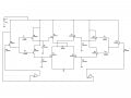
A bit more finished than the last one, although I am missing a few indicators and such. Please keep in mind that it is a rough :) . Let me know if you can spot anything wrong with this one. Thanks again.
 

Attachments

mik3

Joined Feb 4, 2008
4,843
Calvin,
You said you have two motors, one for forward and one for reverse, right? If this is the case then you don't need to make an H bridge driver with the transistors to control the motors. Just use one transistor for each motor and connect the motor terminals in reverse for the one motor as to rotate backwards.
 

Thread Starter

calvintennant

Joined Jan 21, 2009
27
mik3, I've got one motor that is always driving forward. The other motor differentiates between forwards and backwards depending on the state of the phototransistor.

EDIT: each motor drives one wheel, left and right. For the sake of argument lets say the right motor differentiates between forward and backward. In this case when the sensor sees something the right motor will switch to reverse and the robot will spin right. Understand?

This way the robot will be able to turn on a "dime" as the saying goes.

SgtWookie, thanks for the heads up, I'll fix that this afternoon.
 
Last edited:

mik3

Joined Feb 4, 2008
4,843
It looks ok but it would be better if you use MOS instead of BJT transistors. What is the operating current of the motor?
 

Thread Starter

calvintennant

Joined Jan 21, 2009
27
Each motor pulls 200mAh at 4.5V at no load. I'm going to be running the motor at 3V, I expect the motor anywhere between 200-300mAh at this voltage pushing a very small load. Is this realistic?
 

mik3

Joined Feb 4, 2008
4,843
Each motor pulls 200mAh at 4.5V at no load. I'm going to be running the motor at 3V, I expect the motor anywhere between 200-300mAh at this voltage pushing a very small load. Is this realistic?
If the motor draws 200mA at no load it will draw about 500mA with a load (depends on the load of course). If you assume that the lower value of the hfe of the transistors is 10 then you will need a base current of 50mA. If your sensor can supply this amount of current it will be fine. Also, note that when starting the motor it draws more current than when running.
It will be better to build a MOS H-bridge driver or use darlington pair transistors to reduce the base current.
 

mik3

Joined Feb 4, 2008
4,843
What is the difference between MOS and BJT?
In simple words, a BJT transistor needs some amount of continuous current through its base as for current to flow through the emitter. These two currents are related by the gain hfe of the transistor Ic=hfe*Ib.
A MOS transistor does not need a continuous current flow through its gate to turn on. It only draws current when a voltage is applied to its gate until its gate-source capacitance charges. Then only the leakage current flows which is the range of pA.
 

Thread Starter

calvintennant

Joined Jan 21, 2009
27
If the motor draws 200mA at no load it will draw about 500mA with a load (depends on the load of course)
The 200mA at no load is when the motor is running at 4.5V. The motor's operating range is between 3 and 4.5. I plan to be running the motor at 3V, will this effect the current draw?

Also can I run two 3V motors with one 3.7V battery, or should I look at getting a new battery? The battery has a current of 740mA.
 

mik3

Joined Feb 4, 2008
4,843
If you power the motor with 3V it will run at a lower speed than when powered with 4.5V. Also, it will draw more current for the same amount of output power.
You can power the motors from the 3.7V battery but maybe the voltage will drop to less than 3V when the motors are working to the internal resistance of the battery. If you use a more mAh battery it will be better and will give you more working time but try the one you have first.
 

Thread Starter

calvintennant

Joined Jan 21, 2009
27
Alright, I will run my circuit off the 3.7V battery just because I'm running against time and money. I've got to have the whole project done in just a couple of weeks. I might get another batter later, depends on how well it works out and if I want to continue with the project.

What voltage should I run my circuit off of with MOS transistors.
 

mik3

Joined Feb 4, 2008
4,843
As much voltage as the motors need. If you are going to power the whole circuit with a 3.7V battery then forgot the MOS solution. MOS turn fully on with a gate voltage of 5V (for logic level MOS). Thus use darlington pair BJT transistors to make the H bridge.
 

mik3

Joined Feb 4, 2008
4,843
Why would I use darlington transistors/how would I incorporate that into my circuit?
By using a darlington transistor the base current will reduce due to its higher gain. If you don't want to replace all transistors with darlingtons replace only T2 with a darlington one. Another option is to connect another PNP transistor (T6) with T2 to create a darlington pair. To do this disconnect R3 from T2 base, connect T6 emitter to the base of T2, T6 collector to the collector of T2 and connect R3 to the base of T6.
 
Top