Using BJT Transistors as switch for 8x8 LED Matrix display

Thread Starter

Kkein

Joined Jun 10, 2011
46
Hello Folks,
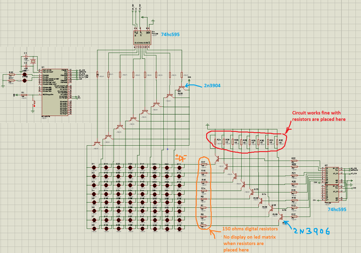
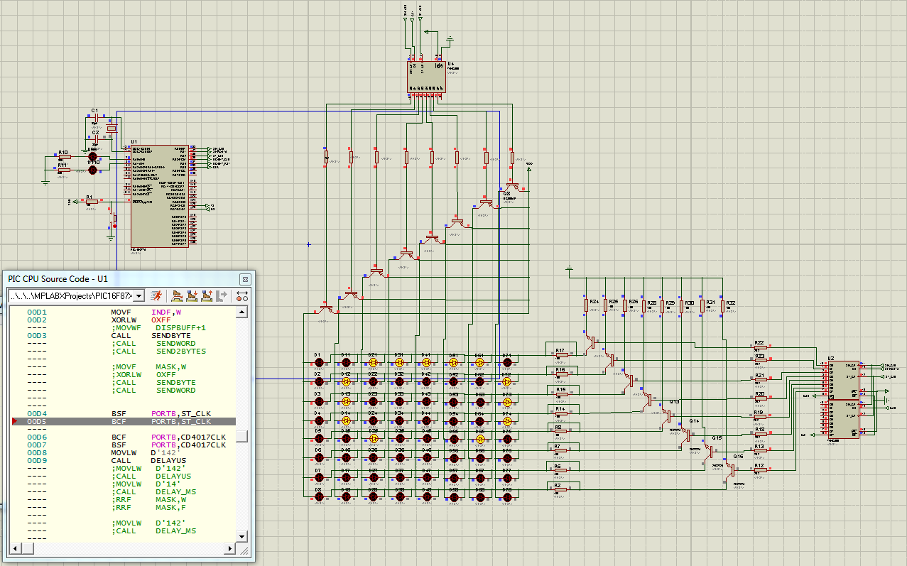
I'm using proteus version 7.9 to simulate 8x8 led matrix and using BJT transistors in sourcing configuration. All load limiting resistors for the leds are digital resistors in the simulation. The placement of the resistive loads create problem for the circuit. When the resistors are placed between the transistors collectors and the common anode side as shown on the diagram, the simulation does not work; LEDs don't light up. But when I placed the digital resistors on the cathode side, (i.e. between the shift registers and cathode side of led matrix), the simulation works fine.
  • the base resistors are 2k7 each,
  • the bypassed load resistors on the collectors, or anode side are 33ohms each
  • the load resistors on the cathode side are 150ohm each
I have not built the breadboard version yet. Is this problem with Proteus software?
Thank you for response.


Last edited:

AnalogKid

Joined Aug 1, 2013
11,037
A single resistor sourcing 8 LEDs will not work well in the real world. Keep the current limiting resistors on the cathode side.
As part of the HC series, the 595 probably cannot sink 20 mA per output.

As a general practice for this type of schematic, move the LED source power and the anode transistors to the top part of the schematic. Power and signals move from left to right and top to bottom. When in conflict, signal flow trumps power flow. I would move the 74HC7595 to the left near the microcontroller, placing more of the system signals together on the left, and the system "output", the display, on the right.

ak
 

Thread Starter

Kkein

Joined Jun 10, 2011
46
Thanks guys. I originally had all NPN transistors, but changed to PNPs and forgot to replace that one!

I concur that I should keep the load resistors on the cathode side because as i now see it, putting 33ohm resistors on the anode side would allow160mA to flow, and the 74HC595 isn't capable of sinking that much current per pin.

However, I'm not sure if moving the power and signals from left to right and top to bottom would change the behavior of the circuit. Is that just to keep things neat?

Also, why aren't the leds in the matrix lighting up when the load resistors are between the cathode and the emitter of current sinking BJT transistors (PNP), but work when the resistors are between the ground and the collectors (see attached)?

Thanks.


Last edited:
Also, why aren't the leds in the matrix lighting up when the load resistors are between the cathode and the emitter of current sinking BJT transistors (PNP), but work when the resistors are between the ground and the collectors (see attached)?
Changing the schematic with power + on top & - on bottom, and signal source on left and signal destination on right just make it easy to read. Upside down ground symbols make the reader work to understand and schematics can be misunderstood if the common layout is not followed.

As for your question about resistor position....

To turn a PNP resistor on (allow current to flow), the base signal must be pulled 0.7 volts below the emitter. How can that be done if the transistor is connected to ground? PNPs are placed closer to the + power rail for that reason. Adding the resistor between the PNP and ground "lifts" the PNP some volts above ground (by current X resistance = volts).

Notice that LIFT is in quotes. It is common to use words like lift and raise when describing voltage of a schematic when the standard layout rules are followed. Since your PNPs are upside down according to standards, saying LIFT can get confusing.
 

Thread Starter

Kkein

Joined Jun 10, 2011
46
Thanks folks. Using PNP for highside does not work for me. I have simplified the simulation by using logic State components and analogue resistors. Here is the circuit. For some reasons, the highside PNP is always ON regardless of the state of logic State. Everything works fine without the PNP. But when I replaced the highside PNP with NPN, it works, however; the current through the LED halved. I suspect Proteus software might be an issue. Kindly help.
Thanks

 
I think your simulator is getting confused by your jumper across the resistor above the PNP.
-or-
Your digital supply connected to the emitter of the PNP may not really be at 5 V (you wrote 5V but did you measure it. If it is set to 12 V, then the PNP will not turn off.

That's all I can think of.
 

Thread Starter

Kkein

Joined Jun 10, 2011
46
Hi folks, got it working. Apparently, 2n3906 was the problem. Everything works when I replaced it with BC556AP. Could be problem with Spice model. Anyone knows how I should update the spice model for this transistor.
Also, the reason why the led matrix did not display anything when the load resistors are between the cathode and the low side npn transistors is because the resistors are digital ones. It works when I changed them to analogue. However, there is too much lags, and proteus couldn't simulate properly. I'm sure it will work well in real life.

Attached is my schematic.

 
Top