Hello Folks,
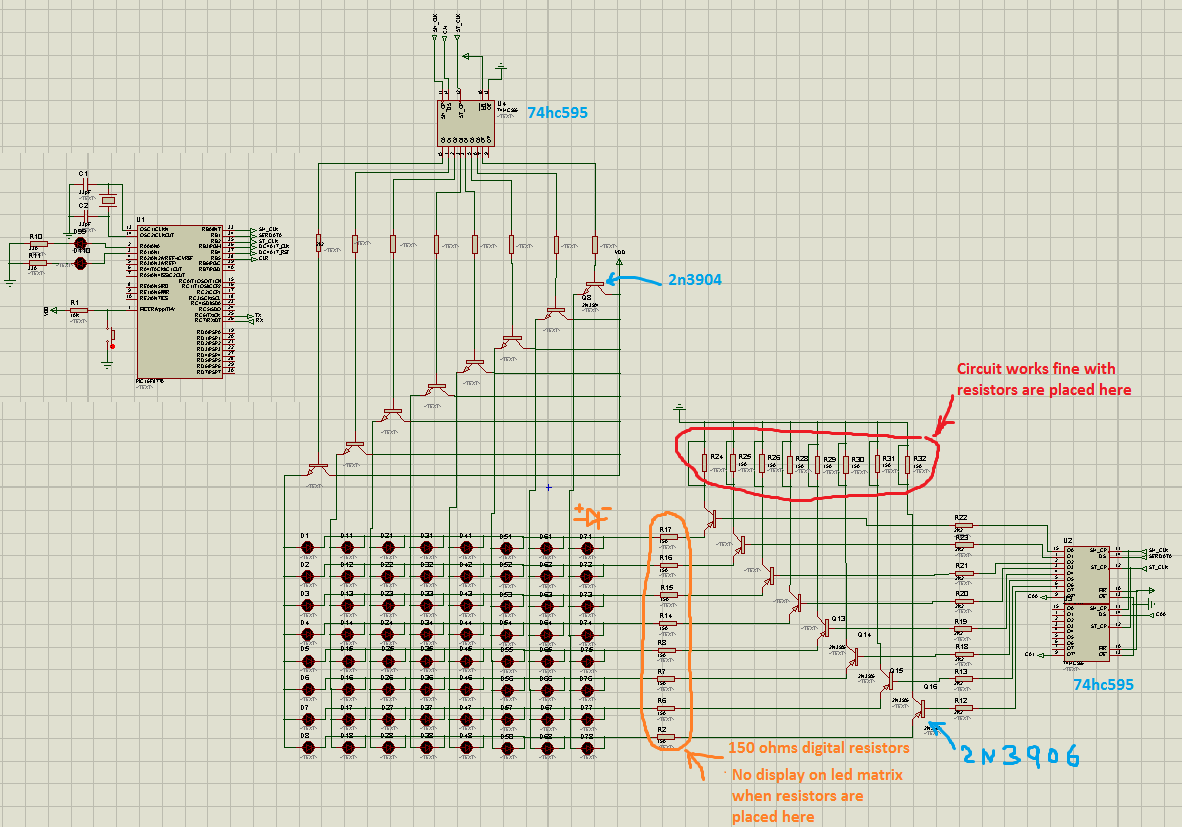
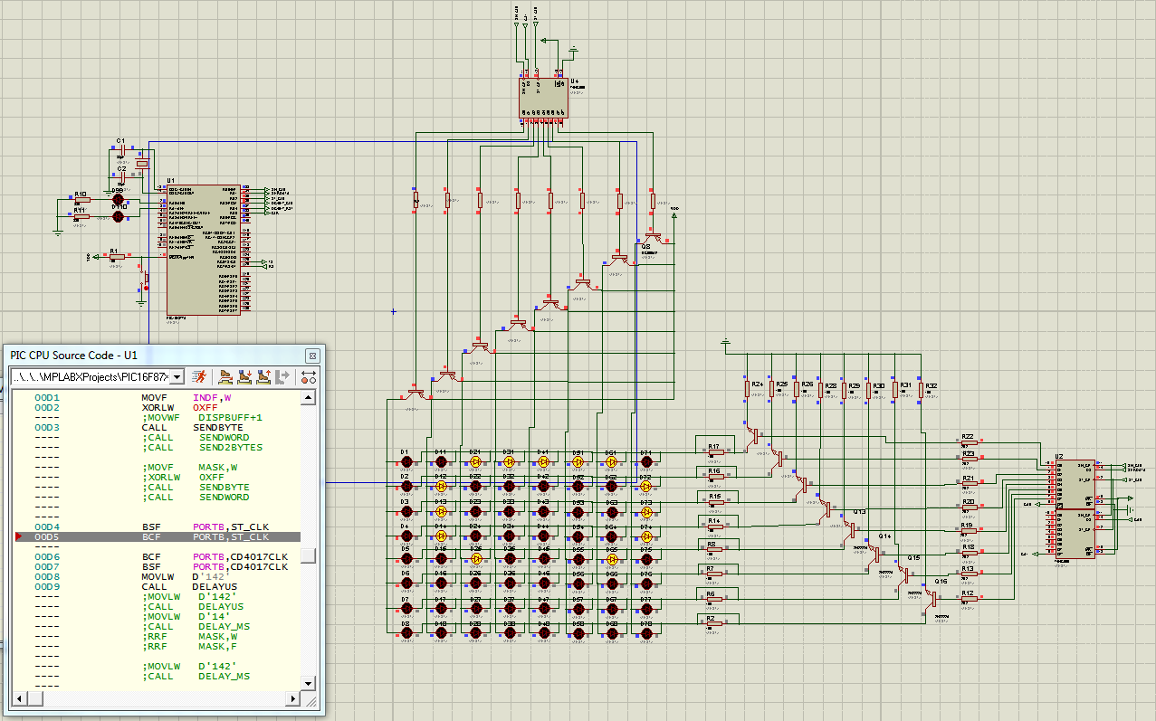
I'm using proteus version 7.9 to simulate 8x8 led matrix and using BJT transistors in sourcing configuration. All load limiting resistors for the leds are digital resistors in the simulation. The placement of the resistive loads create problem for the circuit. When the resistors are placed between the transistors collectors and the common anode side as shown on the diagram, the simulation does not work; LEDs don't light up. But when I placed the digital resistors on the cathode side, (i.e. between the shift registers and cathode side of led matrix), the simulation works fine.
Thank you for response.

I'm using proteus version 7.9 to simulate 8x8 led matrix and using BJT transistors in sourcing configuration. All load limiting resistors for the leds are digital resistors in the simulation. The placement of the resistive loads create problem for the circuit. When the resistors are placed between the transistors collectors and the common anode side as shown on the diagram, the simulation does not work; LEDs don't light up. But when I placed the digital resistors on the cathode side, (i.e. between the shift registers and cathode side of led matrix), the simulation works fine.
- the base resistors are 2k7 each,
- the bypassed load resistors on the collectors, or anode side are 33ohms each
- the load resistors on the cathode side are 150ohm each
Thank you for response.

Last edited:


