Facebook
 Google
 GitHub
 Linkedin
I would like to convert 230 mains voltage to 400 and then rectify it to produce 400V DC.
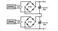
Transformers for that are not common but I have found one that can take 415V in and produce 240V out. Could I simply use this in reverse and then feed that to a standard full wave rectifier?
Thanks
Transformers for that are not common but I have found one that can take 415V in and produce 240V out. Could I simply use this in reverse and then feed that to a standard full wave rectifier?
Thanks
Attachments
-
 149.7 KB Views: 10