Facebook
 Google
 GitHub
 Linkedin

A bit of background first:
I'm trying to make a multipurpose module that will be capable of:
- Flashing two independent outputs at about 0.5 - 1 Hz
- PWM one output at a few kHz
- RS-485-control of two independent outputs. Then it could potentially be instructed to do anything - flash the outputs, continuous-on/off, or PWM. (The RS-485 will go through a transceiver chip, then to the PIC, which will then control the outputs per its programming.)
- The MOSFETs/gate driver must be able to handle anything from 12 to 48VDC.
- Peak current loading per FET will be <2A.
- Logic circuitry runs at 5V.
I'm looking to control a bunch of strings of LEDs, either a cluster of regular T 1-3/4, or else 12 high-brightness 1W LEDs.
Notes: The high-brightness 1W LEDs are driven by a constant current supply; these will not be PWM'd, but may be flashed.
The outputs are to be connected to two loads, which will have a common GND between them.
I've been looking at many different high-side N-channel MOSFETs, and how to go about driving them. Their allure is of course their low on-resistance, but driving the darn things on the high-side seems to have all kinds of challenges, and the fact that they will need to serve in continuous-on duty seems to put a damper on using a driver with a bootstrap type of arrangement, something like the LTC4440-5. They appear to require off-time in order to build up sufficient voltage at the gate output.
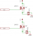
In the attached schematic, that shows a general view of what I'd like to do. The control signals will be coming from a PIC chip. V+ is the input voltage, which will be 12V or 48V, depending on what it's powering. NC1 and NO1 are the connection points for the load.
(Note that the "NO" and "NC" designations are to indicate the default states of the MOSFETs when the circuit is powered-up - the PIC will be programmed to turn on the "NC" MOSFET by default.)
So, given the requirements of PWM and continuous-on control, up to 48VDC input, coupled with the gate drive voltage requirements of high-side N-channel MOSFETs, am I just going to have to bite the bullet and use P-channel MOSFETs? (I think I'd still need some kind of driver chip in order to get acceptable turn-on/off times.)
Thank you in advance.
If any further details are required, I'll be glad to provide what I can. If I need to do some additional reading, which is a distinct possibility, please point me in the right direction.
I'm trying to make a multipurpose module that will be capable of:
- Flashing two independent outputs at about 0.5 - 1 Hz
- PWM one output at a few kHz
- RS-485-control of two independent outputs. Then it could potentially be instructed to do anything - flash the outputs, continuous-on/off, or PWM. (The RS-485 will go through a transceiver chip, then to the PIC, which will then control the outputs per its programming.)
- The MOSFETs/gate driver must be able to handle anything from 12 to 48VDC.
- Peak current loading per FET will be <2A.
- Logic circuitry runs at 5V.
I'm looking to control a bunch of strings of LEDs, either a cluster of regular T 1-3/4, or else 12 high-brightness 1W LEDs.
Notes: The high-brightness 1W LEDs are driven by a constant current supply; these will not be PWM'd, but may be flashed.
The outputs are to be connected to two loads, which will have a common GND between them.
I've been looking at many different high-side N-channel MOSFETs, and how to go about driving them. Their allure is of course their low on-resistance, but driving the darn things on the high-side seems to have all kinds of challenges, and the fact that they will need to serve in continuous-on duty seems to put a damper on using a driver with a bootstrap type of arrangement, something like the LTC4440-5. They appear to require off-time in order to build up sufficient voltage at the gate output.
In the attached schematic, that shows a general view of what I'd like to do. The control signals will be coming from a PIC chip. V+ is the input voltage, which will be 12V or 48V, depending on what it's powering. NC1 and NO1 are the connection points for the load.
(Note that the "NO" and "NC" designations are to indicate the default states of the MOSFETs when the circuit is powered-up - the PIC will be programmed to turn on the "NC" MOSFET by default.)
So, given the requirements of PWM and continuous-on control, up to 48VDC input, coupled with the gate drive voltage requirements of high-side N-channel MOSFETs, am I just going to have to bite the bullet and use P-channel MOSFETs? (I think I'd still need some kind of driver chip in order to get acceptable turn-on/off times.)
Thank you in advance.
If any further details are required, I'll be glad to provide what I can. If I need to do some additional reading, which is a distinct possibility, please point me in the right direction.
Attachments
-
 2.7 KB Views: 43
Last edited: