 Facebook
 Google
 GitHub
 Linkedin
So i am working on a circuits project and i could use some help. The requirements are below and the schematic we need to use is attached. I am just having a hard time starting the project. I need to be able to calculate the values for this circuit to work and any help would be great.
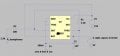
Students need to provide an audio signal that is a function of the light level. Here, a 555 timer is to be used as a voltage controlled oscillator (VCO) that will generate a tone at a frequency of 500 Hz (+/-20%) at zero light level and 1000 Hz at full light (0 volts applied to motor). A small speaker or headset can be used to make the output audible and an oscilloscope can be used to verify the frequencies. One possible circuit is provided in the project data sheets folder (555CVCO.ASC) which can be used as a starting point. The 555 timer should have a frequency range from (~500Hz to ~1500Hz). The schematic below is for the 555 timer.
Students need to provide an audio signal that is a function of the light level. Here, a 555 timer is to be used as a voltage controlled oscillator (VCO) that will generate a tone at a frequency of 500 Hz (+/-20%) at zero light level and 1000 Hz at full light (0 volts applied to motor). A small speaker or headset can be used to make the output audible and an oscilloscope can be used to verify the frequencies. One possible circuit is provided in the project data sheets folder (555CVCO.ASC) which can be used as a starting point. The 555 timer should have a frequency range from (~500Hz to ~1500Hz). The schematic below is for the 555 timer.
Attachments
-
 49 KB Views: 17
 -
 49 KB Views: 14
 -
 49 KB Views: 16


