using a 555 timer as a delay before an alarm is activated

Thread Starter

student2712

Joined Jun 29, 2013
6
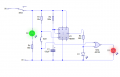
im working on my GCSE project and im making a door alarm and so in one of my circuits ive decided i want to put in a 555 timer to make a delay start so the user can get out of the room before the alarm is activated (it is triggered using a infra-red receiver). i have managed to make the 555 timer part of the circuit but i have no idea how to make it into what i want? I also dont know how to use the infrared receiver, as i havent been taught using the circuit symbol yet, but i have to use it rather than the reed switch and the hall effect which i already have, and the ultrasonic range sensor which will be in the last circuit

can anyone give me a hand with this?? i have to hand everything in by tuesday so asap would be nice :))
 

mbohuntr

Joined Apr 6, 2009
446
I am actually building a similar circuit as part of a burglar alarm and used this 555 circuit with a few mods. It gives a nice 30 second delay and draws next to nothing. I eliminated the transistor, put 6 and 7 high through a 1M resistor, and substituted the 5M resistor with a 1M one. Pin 5 is open, and pin 2 goes through a magnetic switch , and a 1K resistor to the V+. Maybe not a perfect circuit, but as a door delay, works very well. The output at 3 goes thru a 10k resistor to a two transistor latch which is the heart of the circuit. I'm trying to figure out a auto. reset for the alarm with another 555, or a 556. Hope this helps.
 

Thread Starter

student2712

Joined Jun 29, 2013
6
yeah, im a first year at this, so simpler terms would be much appreciated, sorry :p
and would that cater to what i want it to do?
cause you know you have your average house alarm and it has a delay so the person can get out and lock the door before the alarm officially starts detecting movement or whatever, its supposed to work like that, and ive got it to the point where ive used a NOR gate i think it was and it doesnt switch on the alarm part while the green LED is on, saying its safe to be in the room and wont activate it etc

i'll add a pic...theyre in the attachments :p

something like that, add anything to it if you like, i just want to make it work

as in, the red led cant go on before the push to make is switched on, only after

thanks :))
 

Attachments

mbohuntr

Joined Apr 6, 2009
446
The 555 can act as a voltage comparator. I'm not the best to explain this, Probably Bill Marsden is. Basically, the output will change state if the level on pin 2 sees 1/3 Vin, Pin 6 is 2/3 Vin. Read about Monostable operation here. Your using the 1M resistor, cap combination as a decay timer on pin 2. if pin 2 gets disconnected from the circuit for (x) time, the voltage at pin 2 slowly drops below 1/3 Vin and the output goes high. If the door is reclosed before this, the cap recharges and nothing happens. I cannot draw the circuit I described an my multisim program is down right now. Perhaps someone else could draw it from my directions. I can try later today...
 

mbohuntr

Joined Apr 6, 2009
446
Take the monostable pic in the last link I posted and connect a 1M resistor and a 22uF cap in parallel then connect to the bottom of the switch in the pic (to ground). If the switch is held open for (x) seconds, the output at 3 goes high, if the switch is reclosed before then, like a door, nothing happens.
 

mbohuntr

Joined Apr 6, 2009
446
The one that says "switch", not the one that says "reset" ;) I have pin 4 to the Vin, no reset. I also do not have C1 either. A trigger is when you open the switch, taking away the Vin.
 

Thread Starter

student2712

Joined Jun 29, 2013
6
ive just realised that without the IR the circuit will never do what i want it to, because it will always put the red LED on when the SPDT switch is on the second throw, so if anyone knows how i can put in the IR then that would be helpful :)

ive attached what the circuit symbol looks like, and ive looked up circuits with this in but its all really complicated and i dont know how to take it out and incorporate into mine :p

thanks :))
 

Attachments

mbohuntr

Joined Apr 6, 2009
446
The receiver will be the NC switch in the circuit because it "sees" IR light and is conducting. . When the beam is broken for a short period, nothing will happen. No delay. Try a NC door switch instead. I don't understand the logic gates purpose.
 

Thread Starter

student2712

Joined Jun 29, 2013
6
NC switch? i have to use the IR cause ive already used a reed and a hall effect and the four circuits im designing all have to be different :p
 

mbohuntr

Joined Apr 6, 2009
446
Place the (conducting) receiver in place of the switch. Just understand that the door will have to block the beam for (x) seconds before the alarm will sound. I never had any luck w/ ir components in my simulator, I could not get them to conduct in multisim.
 

Thread Starter

student2712

Joined Jun 29, 2013
6
i have no idea what an NC switch is, but i understand the basics of what you're trying to say :p ive never been one for technical talk xD
ive managed to work a way around what i want to do by adding a thyristor and another 555 timer, but has anyone got an idea for an electrical switch to activate a separate circuit or could i use a relay or something? for example, i want to use the thyristor to latch on once the second green LED is turned on, and then the thyristor will activate another 555 timer which will delay the activation of the IR and then that will stay like that until the thyristor is reset, the whole thing is switched off, or the IR is triggered, so sounding the alarm :)

complicated, but its ok in my head, i just need the electric switch and it will work (and how to put in the IR ;) )

thanks :))
 

mbohuntr

Joined Apr 6, 2009
446
NC/NO means "normally open/normally closed. I gave some bad intel, you would have needed a NO switch as the switch will open when the magnet is removed. (Door is opened.) Pretty sure I'm unable to help further... The only delays I understand are cap/resistor decay and charge, and uController stuff. Sorry I couldn't help more.. good luck.
 

tracecom

Joined Apr 16, 2010
3,944
Let me see if I understand what you want.

You have an IR receiver that you want to activate an alarm whenever it detects a warm body in your room. You want to be able to turn the circuit on, but have a 30 second delay before the IR detector can activate the alarm. And you want to use a NE555 IC in this arrangement.

If that is correct, please post a link or specifications for the IR receiver you are using, state what your power source and voltage is going to be, and post a link or specifications to the alarm you are using.

I (or someone here) can post a possible solution.
 
Top