Is it safe to use a resistor divider to output approximately 5v AC from the 120v AC line voltage without a step down transformer to clock my CMOS counter?
What nature of pulse do you need, 50hz/60hz or 100hz/120hz?
If just a clock signal look up the sample circuits for phase angle detection/zero crossing etc and use a opto isolator.
See Fairchild AN-3006 for e.g.
Max.
Is it safe to use a resistor divider to output approximately 5v AC from the 120v AC line voltage without a step down transformer to clock my CMOS counter?
What I've done in the past is use a series of resistors to bring down the appropriate current and voltage to drive an ac optoisolator (such as the SFH620A-3) and then use its output as a clock signal. That would be a safe way of doing it.
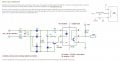
I tried this circuit attached with the transformer voltage at 10 V ac and Vcc at 6.0 V, 8 V, and 10 V. At 6 V the output was 1 hz and at 8 V it was 1 hz but at Vcc of 10 V the output was about 1.5 hertz guessing from looks. Somehow the 60hz line frequency changed. The Schmitt Trigger input of the cd4040 didn't work to shape the pulsating DC so I had to use the independent Schmitt trigger.
Is it safe to use a resistor divider to output approximately 5v AC from the 120v AC line voltage without a step down transformer to clock my CMOS counter?
Is it safe to use a resistor divider to output approximately 5v AC from the 120v AC line voltage without a step down transformer to clock my CMOS counter?
NO, it is not safe. I’m an industrial electrician and play with big power all day, but at home on my bench, anything that comes out of the wall is isolated.
Not only that its not safe, but you can burn the house if you do not know how to calculate the power dissipation over the components.
Why not use a standard transformer for long hour work and a Gretz rectifier after it? If the transformer is not made for long hour work it will overheat and burn the house down also. Something like a bell transformer from the old bells will work, since its made to be active every day the whole day.
With the frequency changing unexplained I am sure we are dealing with the spirit changing the 60 Hertz line frequency by changing the theory and physical constants because it is limited by time.
Not only that its not safe, but you can burn the house if you do not know how to calculate the power dissipation over the components.
Why not use a standard transformer for long hour work and a Gretz rectifier after it? If the transformer is not made for long hour work it will overheat and burn the house down also. Something like a bell transformer from the old bells will work, since its made to be active every day the whole day.
Probably in the USA you will not find such a transformer, but evidently in other parts of the world such things are common. So any transformere should be qualified for constant duty.
With the frequency changing unexplained I am sure we are dealing with the spirit changing the 60 Hertz line frequency by changing the theory and physical constants because it is limited by time.
I don't think the generators at the power plant are changing in speed.
I have had circuits like yours oscillate during the slow transition time of the transistor. The best I can think to try is putting a small capacitor from the collector of the transistor to ground. I would try something like 100 pf.
Let me know if that helps since I don't have time to try it myself.
Get rid of the transistor ahead of the schmitt trigger - it just makes a mess of things by providing gain for noise. Limit the current into the protection diodes at the input of the schmitt with a series resistor in the range a 100k.
There are safety issues in working on a circuit without isolation, but if the entire circuit is properly packaged in an insulating enclosure, it is not unsafe to use.
That was my first thought too, after reading Richard's comment. Seems like the hysteresis a Schmitt trigger provides would be very helpful here, but the transistor totally defeats it.
I'm intrigued by dendad's proposed circuit, but it seems like it would also have slow transitions through the transistor's linear region, risking similar noise issues.
Get rid of the transistor ahead of the schmitt trigger - it just makes a mess of things by providing gain for noise. Limit the current into the protection diodes at the input of the schmitt with a series resistor in the range a 100k.
Don't ever rely on internal transient protection features to behave as circuit components. Among other things, they are poorly documented, vary from one manufacturer to another, and can change without notice. If you have to limit an incoming voltage to a safe level, do it with external components. They cost pennies and save dollars.
The peak voltage value of the waveform out of the bridge can vary significantly for many reasons, many of which are out of your control. True, a saturated switch can change state on a noise glitch and give a false output, but increasing the circuit impedance by 10x or 100x can have a similar effect, even with a Schmitt input. Better to replace the transistor with a zener diode to clip the waveform peaks to a safe value, and keep the series resistor to something much lower than 100K.
Looking back at the original circuit, it seems that part of the problem may be from the input to the schmidt trigger IC exceeding it's supply voltage. When that is done then none of the functional claims apply. I should have spotted that a lot sooner, but the safety concerns distracted me. Since the discrepancy appeared at ten volts in, the best solution would be a clamp-type of voltage limiter on the input..
And I don't think that the purpose of the one pulse per second output was ever mentioned, or explained. That may have an effect on what gets suggested.
 Facebook
 Google
 GitHub
 Linkedin


")


