Used 2000 Ford Mustang Alternator Scenario...

Thread Starter

RandyFL

Joined Aug 28, 2014
148
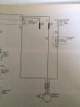
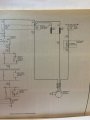
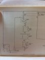
The Haynes 2000 3.8 L V6 schematic is below ( or above )...
My 3 connector wires are:

white/black A.) goes back to the Alt. ...? ( assumption = sensing )
yellow/white B.) goes to the ignition ( switch...... ( Assumption ))
green/red C.) Charge Light ( instrument cluster ( assumption ))

on the schematic... is the black/orange the positive connection of the Alt. ?
and the alt. body is the neg?

Update ( edit ) Did they make a mistake on the schematic in Haynes...?
IMG_2599MustangAltSchematic.JPG

thanx in advance
R

PS did they make a mistake ( I just noticed... trace the wires from the alt./reg ) on the schematic... they don't match.......
 
Last edited:

shortbus

Joined Sep 30, 2009
10,049
Not going to go back through all of the posts, did you say what generation your alternator is? G(en)2, G(en)3 or what? They all work differently. I'm a GM man my self, Ford does some weird stuff compared to GM. Some of the alternators have the regulator as part of the PCM, some have it in the alt body, older ones a separate module. In your schematic, where does the red wire lead to? The one on the other side of alt fuse.

What is your end expectation in this "experiment"?
 

Thread Starter

RandyFL

Joined Aug 28, 2014
148
Not going to go back through all of the posts, did you say what generation your alternator is? G(en)2, G(en)3 or what? They all work differently. I'm a GM man my self, Ford does some weird stuff compared to GM. Some of the alternators have the regulator as part of the PCM, some have it in the alt body, older ones a separate module. In your schematic, where does the red wire lead to? The one on the other side of alt fuse.

What is your end expectation in this "experiment"?
from what I gathered from the posts... its a gen 3
the big red wire is the positive ( edit ) let me check the schematic

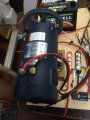
my goal in this ... is to see if this Alt. ( spare 2000 mustang alt. ) is capable of running a DC 12 motor ^ stated above

thanx in advance
R
ps if the answer is " yes " I have to see it
if the answer is " no " I still have to see it ... break down, burn up , smoke... or whatever...
 
Last edited:

shortbus

Joined Sep 30, 2009
10,049
you guys scared me... I thought there was going to be a argumentative debate ( as I was going along my busy day reading with my iPhone ( to keep up on things here ))...
so let's list the things we know so far about my particular project...
1. the alternator has to have an initial source of voltage ( to produce emf )
2. the alternator has be spun a X amount of spin to function as a generator ( alternator ) of additional emf
3. the load determines the amount of emf to be produced by way of the internal regulator
4. The sensing wire has to be connected so the internal regulator functions correctly
please correct these if need be, add to the list if need be and or subtract what needs to be...

R
Can answer some of the questions.

1. The initial excitation comes through the idiot light on the dash. If the light burns out alt won't charge. Once charge starts, there is battery voltage on both sides of the bulb and light goes out.

2.As long as the alt has excitation to the rotor(idiot light) and is turning, it is putting out voltage, barring other problems/faults in the alt. It won't necessarily be high enough to charge battery or run accessories in car, but voltage will be at output point. Doesn't start to put real or rated current until a higher RPM.

3. Not necessarily, regulator does regulate, but it isn't always internal to the alt. Some are separate, mechanical(older type), a solid state module or it can be part of the PCM or ECM.

4. see #3

Guess I could answer all of them.
 

shortbus

Joined Sep 30, 2009
10,049
from what I gathered from the posts... its a gen 3
the big red wire is the positive

my goal in this ... is to see if this Alt. ( spare 2000 mustang alt. ) is capable of running a DC 12 motor ^ stated above
What motor and what is running the alt? Don't think that is how you tell the generation of the alt. All output leads are red. At least if they are OEM. I have read this from the start, just gets so confusing what is being done as the days go by.
 

Thread Starter

RandyFL

Joined Aug 28, 2014
148
1. The initial excitation comes through the idiot light on the dash. If the light burns out alt won't charge. Once charge starts, there is battery voltage on both sides of the bulb and light goes out.
Its been stated that a bulb 194 will do... does there have to be a resistor attached to it...

3. Not necessarily, regulator does regulate, but it isn't always internal to the alt. Some are separate, mechanical(older type), a solid state module or it can be part of the PCM or ECM.
Internal voltage regulator on a gen 3 alt.

R
 

Thread Starter

RandyFL

Joined Aug 28, 2014
148
Here's what we know...
Green goes to a light bulb ( 194 ) with a 500 ohm resistor ( in parallel ) to a fuse and then the positive side of battery
White goes back to the stator
yellow goes to a switch ( ignition - in cars ) and to a fuse and then to the positive side of a battery
Red goes to a fuse ( assumption ) and then to the positive
fuses 20 amp...?

Correct...?

thanx in advance

R
ps can anybody draw this in a circuit ( I sux at that )...?
 

Tonyr1084

Joined Sep 24, 2015
9,744
Without having the Haynes in hand I can only guess that the red wire is probably a battery bus, meaning everything electrical is powered from that bus. Follow the red wire off the page. At the side of the page it should tell you where the schematic picks up and you can continue to follow the red wire to its source (or destination). It's been many many years since I owned and operated a Ford. I grew up a Chevy guy and of late have become a fan of foreign; mostly Toyota. Two of them sit in the driveway now.

Schematics are another language; one that can serve you well. In fact, often I can understand more from the schematic than I can from the author's paragraph on what it does. Draw it out (pencil and paper) and study it. If you see something wrong, correct it. Build upon what you know and the rest should fall into place.

To be honest, I'm still having a hard time figuring out why you want to generate 12 volts using a 12 volt source. But like I said before - you know your goals. Still, it would help if you could be a little less vague about what you want to accomplish and why. It seems like you're spending a whole lot of time on this - and possibly money too. It's a rather expensive lab if that's all it is. So if there's a purpose to this, I'd like to understand what it is.
 

shortbus

Joined Sep 30, 2009
10,049
To be honest, I'm still having a hard time figuring out why you want to generate 12 volts using a 12 volt source. But like I said before - you know your goals. Still, it would help if you could be a little less vague about what you want to accomplish and why. It seems like you're spending a whole lot of time on this - and possibly money too. It's a rather expensive lab if that's all it is. So if there's a purpose to this, I'd like to understand what it is.
I agree with this. RandyFl is starting to sound/look like a troll.:( Instead of Googling and doing his own homework, he is using the members on the forum. He can't want this to work very much.
 

Tonyr1084

Joined Sep 24, 2015
9,744
I wouldn't say "Troll" however, I remain suspicious he's still trying to create an Over-Unity machine. Or maybe he's trying to have US create it for him.

Randy: What's up? What are you trying to do? Please help us understand so we can help you.
 

Thread Starter

RandyFL

Joined Aug 28, 2014
148
1. I wanted to know if a alternator can power it self by generating 12 volts...
a. The 12 volt DC motor is already running ( its running off the battery )
b. If the front of the 12 Volt DC motor is powering the Alt. ... what's the back end doing...
c. the back end of the 12 Volt DC motor is enclosed ( but its still spinning )
d. larger DC and AC motors have open or closed ends ( they generate heat - I know - how much ... I don't know...)
2. Can the alternator be made into a motor...
a. If the alternator can be made into a motor
1. Can the torque be adjustable
3. If the alternator can be made into a motor
a. Can two alternators be made into a sychnous unit

shall I go on...

R
 
Top