 Facebook
 Google
 GitHub
 Linkedin
Over the past week I tried to make this Instructable: USB Powered Speaker. I thought it would be nice to have a speaker with an IC and adjustable volume, and was interested in the idea of powering it from a USB port rather than a battery.

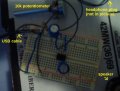
I tried assembling this circuit on a breadboard, but it's not working for some reason. I've tried various things, including powering the circuit with a 9V battery rather than a USB port, but with no success. Perhaps the LM386 chip I'm using is blown, but it wasn't when I checked it a few days ago.
Attached are two pictures of my setup. Sorry for the poor image quality, but I'm hoping they can be of some help in diagnosing the problem.
Attachments
-
 209.5 KB Views: 39
 -
 209.8 KB Views: 42
Last edited:


