Facebook
 Google
 GitHub
 Linkedin
Really new to the circuit building/electronics area so please bear any elementary questions and mistakes!
I've searched the web and have found schematics for other uses but can't seem to adjust them to my purpose, at least without causing some nasty stuff which I can't afford!
I have a device that can be connected via RS-232 and USB to a PC so as to send/receive data.
The operation is pretty simple for the Serial as it employs Rx, Tx and Ground, while the USB uses all four connections. In reality the Serial connection is only used for sending data to the PC (i.e. no Rx on the device so I can skip this).
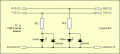
As the device is physically located in a cramped space without easy visual reference, I want to place an "intermediate" panel with plugs for the Serial and USB cables near the PC. In order to at least see if the data is flowing, I want to build a (or two) circuit(s) and have two LEDs apiece to indicate data flow from the USB/Serial to the PC and vice versa.
As I mentioned I've found schematics mostly for USB but I'm a bit confused with the resistors required plus I'm not sure if the data signals will get degraded (which I don't want). Things get more complicated with the Serial signals as the actual data are in the 0 to -13V area so if I understand correctly I'll have to use a diode to get the LED working.
I've also found many schematics that employ microcontrollers which I really don't need for this project. So basically just a "pass through" circuit for data flow indication without degrading the signals before they reach the PC.
Any help would be greatly appreciated!
I've searched the web and have found schematics for other uses but can't seem to adjust them to my purpose, at least without causing some nasty stuff which I can't afford!
I have a device that can be connected via RS-232 and USB to a PC so as to send/receive data.
The operation is pretty simple for the Serial as it employs Rx, Tx and Ground, while the USB uses all four connections. In reality the Serial connection is only used for sending data to the PC (i.e. no Rx on the device so I can skip this).
As the device is physically located in a cramped space without easy visual reference, I want to place an "intermediate" panel with plugs for the Serial and USB cables near the PC. In order to at least see if the data is flowing, I want to build a (or two) circuit(s) and have two LEDs apiece to indicate data flow from the USB/Serial to the PC and vice versa.
As I mentioned I've found schematics mostly for USB but I'm a bit confused with the resistors required plus I'm not sure if the data signals will get degraded (which I don't want). Things get more complicated with the Serial signals as the actual data are in the 0 to -13V area so if I understand correctly I'll have to use a diode to get the LED working.
I've also found many schematics that employ microcontrollers which I really don't need for this project. So basically just a "pass through" circuit for data flow indication without degrading the signals before they reach the PC.
Any help would be greatly appreciated!