 Facebook
 Google
 GitHub
 Linkedin
Hello everybody.
Please I need your Priceless guidance
First of all I am not an Electronic Student.
I learnt the little I know by reading online, asking questions and doing self-monitored practicals in my small room.
I want to build a device that boost Power Supply from a smaller AC source (e.g 500W Inverter, 650W Gasoline Generator) to higher level high enough to power resistive loads like Pressing Iron, Electric Cooker, Hot Air Gun etc.
Why?
In my country with low standard of living, there is no regular supply of Government controlled Power Supply. So majority of people like me choose to generating Electricity themselves whenever they need it to do important things. And the chepeast availble means is to buy a gasoline generator of 650W. But the 650W power output is too low to power Pressing Iron and other resistive load types.
So I thougth of finding a way to boost the Current as that is really what as to bé boosted in order to achieve ones goal.
Through my several reseach online, I discovered that when Diode and Capacitor are used to Convert AC to DC, the Current Increases. But the output current is neither real DC nor AC; it's always PULSING.
Now I then thougth of it that if such is the case, then a Power Booster can bé made from such discovery using High Capcitance AC Capacitors and Befitting Diodes.
While thinking of this, I discovered a readymade circuit on http://homemadecircuitsandschematic...neratoralternator-ac-voltage-booster.html?m=1 which the designer said it works as a Booster.
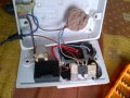
I bougth the primay components which are 2 IN4007 1000V Diodes and 2 475J 400V AC capacitors. The Diodes are connected in series and the Capacitors too are connected in series. The 2 remaining legs on the Capcitors and Diodes are now connetively paired as seen in the Circuits above.
I powered the Set-up with 240AC and took a reading of the output Voltage and was surprised to discovered that the Output was as high as 540V.
At this junction, I now came up with the Idea of reducing the Voltage with 2 Resitors of same Ohm rating of 120K 1W to usable safe level of 200V to 300V.
Yes I was able to reduce the Voltage but I could not Power anything with the resulting Voltage.
Please people why could this bé??
I learnt Resistors primarily works to reduce Current flow in a Circuit by dividing it so could it bé that the 120KOhms resistors I used in dividing the voltage is responsible for the Low output current?
If yes,will it bé appropite to connect in Series two 1Ohm resistor like this ones here http://www.aliexpress.com/wholesale...0150120105831&SearchText=1+ohm+50W++resistor+ to simply divide the voltage and leave the output current untouched?
If yes, where will it bé most appropite to apply the Resistors?
At the Output level as seen in Circuit 1 or at the Input Level as seen in Circuit 2?
If I use 2 1Ohm resistors connected in series to divide the voltage, will it actually leave to Current untouched or will it divide it still?
Please help me out by answering my questions 1-by-1
:::::::::::
Now as for the main Output Voltage type both in Circuit 1 and 2 which is in Pulsing DC or Pulsing AC, how can I successfully Convert it to real AC?
What are the available ways both cheap and costly?
:::::::::::
Thank you everyone in view as you relief me of my Conc Curiousity.

Please I need your Priceless guidance
First of all I am not an Electronic Student.
I learnt the little I know by reading online, asking questions and doing self-monitored practicals in my small room.
I want to build a device that boost Power Supply from a smaller AC source (e.g 500W Inverter, 650W Gasoline Generator) to higher level high enough to power resistive loads like Pressing Iron, Electric Cooker, Hot Air Gun etc.
Why?
In my country with low standard of living, there is no regular supply of Government controlled Power Supply. So majority of people like me choose to generating Electricity themselves whenever they need it to do important things. And the chepeast availble means is to buy a gasoline generator of 650W. But the 650W power output is too low to power Pressing Iron and other resistive load types.
So I thougth of finding a way to boost the Current as that is really what as to bé boosted in order to achieve ones goal.
Through my several reseach online, I discovered that when Diode and Capacitor are used to Convert AC to DC, the Current Increases. But the output current is neither real DC nor AC; it's always PULSING.
Now I then thougth of it that if such is the case, then a Power Booster can bé made from such discovery using High Capcitance AC Capacitors and Befitting Diodes.
While thinking of this, I discovered a readymade circuit on http://homemadecircuitsandschematic...neratoralternator-ac-voltage-booster.html?m=1 which the designer said it works as a Booster.
I bougth the primay components which are 2 IN4007 1000V Diodes and 2 475J 400V AC capacitors. The Diodes are connected in series and the Capacitors too are connected in series. The 2 remaining legs on the Capcitors and Diodes are now connetively paired as seen in the Circuits above.
I powered the Set-up with 240AC and took a reading of the output Voltage and was surprised to discovered that the Output was as high as 540V.
At this junction, I now came up with the Idea of reducing the Voltage with 2 Resitors of same Ohm rating of 120K 1W to usable safe level of 200V to 300V.
Yes I was able to reduce the Voltage but I could not Power anything with the resulting Voltage.
Please people why could this bé??
I learnt Resistors primarily works to reduce Current flow in a Circuit by dividing it so could it bé that the 120KOhms resistors I used in dividing the voltage is responsible for the Low output current?
If yes,will it bé appropite to connect in Series two 1Ohm resistor like this ones here http://www.aliexpress.com/wholesale...0150120105831&SearchText=1+ohm+50W++resistor+ to simply divide the voltage and leave the output current untouched?
If yes, where will it bé most appropite to apply the Resistors?
At the Output level as seen in Circuit 1 or at the Input Level as seen in Circuit 2?
If I use 2 1Ohm resistors connected in series to divide the voltage, will it actually leave to Current untouched or will it divide it still?
Please help me out by answering my questions 1-by-1
:::::::::::
Now as for the main Output Voltage type both in Circuit 1 and 2 which is in Pulsing DC or Pulsing AC, how can I successfully Convert it to real AC?
What are the available ways both cheap and costly?
:::::::::::
Thank you everyone in view as you relief me of my Conc Curiousity.
Last edited:

")


