 Facebook
 Google
 GitHub
 Linkedin
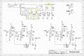
When I first purchased this Little Bear T10 Pro 6N2 valve Phono Turntable RIAA Preamp preamplifier Ver2.5 I did no electrical mods. Just bought Fisher Telefunkens and a Russian Rectifier tube off Ebay. Bought tube damper rings and feet. New audiophile power cable from Audio Advisor and enjoyed it for a few months. I never got the dreaded hum issue that some other buys experienced. Then I decided to recap and replace all the caps and resistors on the signal DC side. Attached is the schematics.
My first step from stock I soldered in the following Caps and the Little Bear worked great. I did not measure these caps when I first put them in.
MUNDORF - MEAIO-0.47, 0.47uF 450V, Mcap EVO Oil Series
Two AMTRANS- 100pF, 100VDC, AMCH Polypropylene Film Cap
Two AMTRANS - 0.1uF 630V, Amtrans AMCO Metalized Polyester (PET) Caps. Success@!
Sounded great with no problems. My soldering skills are good enough. I successfully completed several learning to solder kits before attempting this. Including my Enron? Power transformer kit that is well regarded for students in EE school.
But then I attempted to do the entire signal side by replacing all the resistors. I soldered everything at 430 degree F. With Wonder Solder. That's when disaster stuck! No audio coming out from the preamp.
In answer to your questions I commented below:
1. I was performing a continuity test with my DMM. black probe on the AC ground input and using the red probe to trace the circuits. I could make the schematic with where I probed and report if I got a beep or not. It would be helpful in my understanding how circuits work. I wish I took an actual Electronics course and brought this in to have the teacher got over it with me.
2. I examined all the solder joints with my magnifying professional workbench light and examine each solder joint. They all seems fine to me. I did a few touch ups just in case.
3. Used my multimeter to test the RCA jacks and there was a signal.
4. All my tubes glow the typical strength. I swapped the tubes around several times. They all glow.
5. "The fact that the valves glow means that the heater circuit is OK. What about the HT circuit ? Check across the leads of the same color from the transformer with the DMM on AC."
- I measured all the power leads coming off of the E-Transformer. Within specs so no problem there. my DMM and report the transformer ac output and further readings along the circuit.
The little caps do not measure right. I used my new Craftsmen Multimeter with one log unsoldered from the circuit board to measure the capacitance.
C15, C16 - measured 80 pF - AMTRAMS-73776 100pF 100VDC 630V, Amtrans AMCO Metalized Polyester (PET) Caps
C9 , C10 - measured .093 uF - AMTRAMS-75772 0.1uF 100VDC 630V, Amtrans AMCO Metalized Polyester (PET) Caps
MUNDORF-76426 MEAIO 0.47uF 450v
C19, C20 - measured 70 pF - Capacitor - Silver Mica, 500 V, 10pF - 1000pF - Capacitance: 10 pF
C13, C14 - measured 370 pf
C7, C8, C11 - measured .47 uF
C12 - measured way off at .007 uF (so I guess I need to buy a new cap at this position. Im wonder if I somehow fried it in my soldering and or testing)
Resistors:
Location: Near R23 and R9 - MUNDORF - MEAIO, 0.47uF 450V, Mcap EVO Oil Series
Location: Near R9: - AMTRANS- 100pF, 100VDC, AMCH Polypropylene Film Cap, gold-plated OFHC Leads
Location: R24 - KIWAME Resistor 220R / 2 watt, 1.0%, Axial, Tinned Copper Leads, Flameproof Silicone Coated
Location: R8, R6, R3, R10, R12, R14 - PRP Resistor 3M3 / 0.5 (1/2) Watt, Metal Film, 1%, 100ppm, Non-Magnetic – All failed
Location: R9 - KIWAME Resistor 910R / 2 watt, 1.0%, Axial, Tinned Copper Leads, Flameproof Silicone Coated
Location: R18, R11 - KIWAME Resistor 2K2 / 2 watt, 1.0%, Axial, Tinned Copper Leads, Flameproof Silicone
Location: R16, R5, R2 - KIWAME Resistor 62K / 2 watt, 1.0%, Axial, Tinned Copper Leads, Flameproof Silicone
Location: R7 - PRP Resistor_62499 100R / 1 Watt , Metal Film, 1%, 100ppm
Location: R15, R23 - KIWAME Resistor 330K / 2 watt, 1.0%, Axial, Tinned Copper Leads, Flameproof Silicone – All failed
Then I decided to replace all these KIWAME (carbon) resistors with Takman REY (Poly) resistors. Still no audio coming out of the preamp.
These are my readings for the following Resistors on my v2.5 little bear (test bed phono preamp)
R3 3.3m reads 1.66m
R6 3.3m reads 1.66m
R10 3.3m reads 1.66m
R8 3.3m reads 1.66m
R12 3.3m
R14 3.3m
R24 2.2k reads 1.93k
R25 2.2k reads 1.93k
On my new Little Bear T10 v2.6 I couldn't get any readings at all on the following resistors. But I could on my test bed v2.5 phono stage. My v2.6 works perfectly fine. I cannot figure out why there are not Multimeter Vdc readings. This is impossible to figure out. sigh.
R22, R23, R15 and there are a few more on that side of the board. I gave up trying to measure them.
My next step is to repopulated the original 10 and 100 pF disc capacitors. tonight I plan to solder those in at C15, C16, C19, C20.
I checked the three tube type switches several times. Right now I have 3 Fisher telefunken 12ax7a tubes and a new rectifier from Russia. I need to try the stock Chinese 6N2 tubes next and flip those switches. I replaced every resistor except 4 of them. I also used a table top lighted work bench magnifying glass and all the soldier joints seem fine. Also didn't see any splash over solder making a short. I'm pretty good at that after learning on the 3 kits I built already for practice. I built that Enron power transformer and it worked the first time.
I purchased a new Craftsmen Multimeter that measures capacitance at Sears. I'm a little irked that my EXTECH EX320 doesn't. I bought it to learn and had no idea it couldn't.
Got a new Craftsmen Multimeter that does measure capacitance. Made a bunch of measurements with the caps unsoldered from the board. Many of the new parts are way off!


")


