Tracing source wires in ION Boombox (cassette, radio, aux, Bluetooth) for ZK-1002T amp upgrade

Thread Starter

anarier

Joined Nov 13, 2025
15
Hello everyone,
I’m upgrading the amplifier section of an ION Boombox (board marked T21897A / LT-BT305A AMP, V1.0 20190527) and need guidance on properly tracing and identifying the wires coming from the different sources:
  • Cassette player
  • Radio tuner
  • Aux input
  • Bluetooth module
  • Other internal connections
My goal is to determine which wires can be removed or rerouted so I can feed the correct signals into a new internal amplifier (ZK-1002T). I’d love to replace the underpowered stock amp while keeping all sources working through the new one.
So far, I’ve:
  • Traced some of the preamp inputs visually on the amp board.
  • Integrated a 5 kHz high-pass crossover to protect new tweeters.
  • Replaced speakers with full-range ones for improved sound.
What I’m unsure about is the best method to systematically identify each wire’s function (signal vs. ground, left vs. right channel, etc.) without relying only on trial and error. I don’t have an oscilloscope, but I do have a multimeter and can follow step-by-step probing instructions.
Questions:
  1. What’s the most reliable way to trace and confirm each source wire (cassette, radio, aux, Bluetooth) back to the preamp/amp section using basic tools?
  2. Are there recommended techniques (continuity testing, audio probe, etc.) for verifying audio paths without an oscilloscope?
  3. Once identified, how should I decide which connections to keep or bypass when integrating the new amp?
Any advice, schematics, or step-by-step methods would be greatly appreciated. I’ll also be documenting this process for a YouTube walkthrough and will share back results and diagrams for clarity and reproducibility.
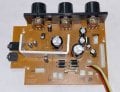
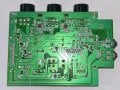
See attached front and back pics of the current amp board.
Thanks in advance for any guidance or help!
Best regards,
Andy
 

Attachments

MrChips

Joined Oct 2, 2009
34,626
Without seeing the circuit schematics, I would imagine that all audio channels are multiplexed into one (or a pair for stereo) using a single chip multiplexer. You don't have to trace all the signals. All you need to do is find the output of the multiplexer that feeds into the power amp.

Look for a multiplexer chip on the board.
 

Thread Starter

anarier

Joined Nov 13, 2025
15
Hi, and thanks for the reply. I emailed the company that made the Boombox, and they say they do not provide schematics. I'm a newbie and don't know what a multiplexer is or what it looks like. Can you give me some tips or a picture, maybe, so I can identify it on my board?
 

MrChips

Joined Oct 2, 2009
34,626
The information you are seeking should be right there on connector CN15.

The stereo input signals are labelled AUXR and AUXL. Ground is A-G. You could leave the board where it is and just set the VOLUME knob to zero. You can also send a signal to MUTE to turn off the amplifier. You will have to check with a voltmeter what voltage is required to mute the amp.

The IC power amplifier is screwed on to the heat sink. Take a well focused photograph of the IC so that we can identify it.


ION Boombox power amp CN15.jpg
 

Thread Starter

anarier

Joined Nov 13, 2025
15
Hi, thanks for the reply. I'm sorry, but I do not see any names near the chip. Is there any other way to isolate the components that connect to his amp board so I can connect them to my new amp?
 

Thread Starter

anarier

Joined Nov 13, 2025
15
This is all good stuff! I will post a his-res pic of it and have more info tonight when I get home. keep the ideas coming in!
Thanks to all.
Andy
 

Thread Starter

anarier

Joined Nov 13, 2025
15
The IC and track layout on the board matches the pinout of TDA7266 IC amplifier.

View attachment 358833
Hello again, could you explain a little more about what I’m seeing in this diagram? Am I correct in assuming (though I might be wrong) that the inputs labeled IN1 and IN2 are coming into the IC chip from the preamp? Also, what should I do with the ST-BY and MUTE inputs? Finally, where should I tap into feed the new amp and bypass this one? I’m sorry if I sound unfamiliar with these circuits; the truth is that I am, but I’m willing to learn and give it a try if I’m guided on what to do. Thanks.
 

LesJones

Joined Jan 8, 2017
4,511
I assume that the power amplifier device on device that you are modifying is the TDA7266 and that you want to replace this with a different power ampliier. (ZK-1002T) You do not need to work out how the input multipexing is done. You only need to extract the the left and right signals thet drive thre existing power ampifier and connect them to the inputs on the new power amplifier.
First remove the existing power amplifier IC. (The TDA7266) Then use a 2 core and screen cable to connect to the ZK-1002T inputs. One core of the screened cable needsto be connected to the pad where pi 4 of the TDA7266 was connected. the other core of the screened cable connect where pin 12 of the TDA7266 was connected. the screen on the cable needs to be connected to where pin 9 of the TDA7266 was connected. the other end of the screened cable goes to a 3.5mm jack plug to plug int the input connection on the ZK-1002T .

Les.
 
Last edited:

MrChips

Joined Oct 2, 2009
34,626
I attempted to identify the on-board IC amplifier in order to determine the required voltage to mute the amp.
The MUTE signal from CN15 goes to a transistor before being applied to the MUTE on pin-6 of the IC. Hence I do not know if the transistor inverts the logic of the MUTE signal. You will have to experiment with this. Normally, you connect MUTE to GND to mute the amplifier. Try both +5 V and GND at CN15 to see which one mutes the amp.

I would leave the TDA7266 in place and just apply MUTE and ST-BY.

Get the signals AUXR and AUXL from CN15 and feed these (along with A-G) to your add-on power amplifier.

You could do what LesJones has suggested. In this way, the original VOLUME and TONE controls are still usable.
 

Thread Starter

anarier

Joined Nov 13, 2025
15
I assume that the power amplifier device on device that you are modifying is the TDA7266 and that you want to replace this with a different power ampliier. (ZK-1002T) You do not need to work out how the input multipexing is done. You only need to extract the the left and right signals thet drive thre existing power ampifier and connect them to the inputs on the new power amplifier.
First remove the existing power amplifier IC. (The TDA7266) Then use a 2 core and screen cable to connect to the ZK-1002T inputs. One core of the screened cable needsto be connected to the pad where pi 4 of the TDA7266 was connected. the other core of the screened cable connect where pin 9 of the TDA7266 was connected. the screen on the cable needs to be connected to where pin 12 of the TDA7266 was connected. the other end of the screened cable goes to a 3.5mm jack plug to plug int the input connection on the ZK-1002T .

Les.
That is awesome, thanks! Would you mind drawing a little diagram of the connections so I can follow it along?
 

Thread Starter

anarier

Joined Nov 13, 2025
15
I attempted to identify the on-board IC amplifier in order to determine the required voltage to mute the amp.
The MUTE signal from CN15 goes to a transistor before being applied to the MUTE on pin-6 of the IC. Hence I do not know if the transistor inverts the logic of the MUTE signal. You will have to experiment with this. Normally, you connect MUTE to GND to mute the amplifier. Try both +5 V and GND at CN15 to see which one mutes the amp.

I would leave the TDA7266 in place and just apply MUTE and ST-BY.

Get the signals AUXR and AUXL from CN15 and feed these (along with A-G) to your add-on power amplifier.

You could do what LesJones has suggested. In this way, the original VOLUME and TONE controls are still usable.
I will check all those details and post back the results. Thanks again!
 

Thread Starter

anarier

Joined Nov 13, 2025
15
Hi all again, and thanks for all your inputs. So by doing this, tapping into the chip's output to get the speakers and tweeters connected with the screened cable to the new amp, I will also need to remove the original amp's speaker output connections, right?
 
Top