[UPDATED] How should I power a 12V-DC, 12.3A LED circuit?

MisterBill2

Joined Jan 23, 2018
28,065
Even if the voltage is stable, i still think that it's a bad idea to try to compensate for the voltage drop with extra voltage on the psu. An adjustable supply, or one with a "weird" voltage is likely to cost more than the typical 12v psu. That money could be used to buy the correct cable, and problem solved. That's a better solution than overloading a thinner cable.
That is true, but if there was a need to do it there is a way to do it right.
 

Reloadron

Joined Jan 15, 2015
7,908
Looking at the general data sheets on the LED strings of 300 LEDs each when powered with 12 VDC they will draw about 4.? Amps per strip. I forget your exact strip data. Using some overhead let's say 5 amps per strip. My original understanding was 10 foot cable runs. Initially looking at AWG 18 copper wire a 10' run would be 20' round trip and that would have a resistance of about 0.1277 Ohms. If we assume 5 amp load you get an I * R Drop of 5.0 * 0.1277 = 0.6 volt. The AWG 18 will handle the approximated 5 amps.

The 0.6 volt loss is not going to matter. I have used strings of RGB 5050 LEDs in automotive applications listed as 12 volt and they ran fine between 12.6 and 13.6 volts. Even using PWM at a stable 12 VDC between a PWM of 80% to 100% you could not, not with my eye anyway, note any discernible difference in intensity.

PWM is all about an average voltage and current. Yes, as you dim the lights reducing the PWM pulse width the average voltage will drop and subsequently the average current so yes, since the current through the lines drops the voltage drop of the lines will drop. So yes, with a fixed output power supply the LEDs will see slightly more voltage but the question is how much will it effect the LEDs and their intensity? With your strings I really don't know how much. I know when I was doing similar with 5050 LEDs it didn't matter enough to matter,

Your options are run with power supplies using external sense tied to the load or run a heavier gauge cable to your loads (LEDs). Experiment with a single string.

Ron
 

Thread Starter

-Ty-

Joined Feb 5, 2017
83
Yes, as you dim the lights reducing the PWM pulse width the average voltage will drop and subsequently the average current so yes, since the current through the lines drops the voltage drop of the lines will drop. So yes, with a fixed output power supply the LEDs will see slightly more voltage
Not that I dont appreciate your response, Ron, but see, now AGAIN here's someone who is saying the exact opposite of others on the forums.

I don't know who or what to believe anymore. Some say a lowered PWM duty cycle will not lead to an increased voltage at the load and provide seemingly scientific explanation as for why it wont, while others say it will. What is going on here? Why is there so much disagreement over this?
 

BobTPH

Joined Jun 5, 2013
11,619
Not every poster in these forums is correct all the time. I have made my share of errors, and always admit it when corrected. Some people think PWM lowers the voltage and current. It lowers the on time. During the on time, the voltage and current are unchanged from what you would see with 100% duty cycle.

You can make PWM produce a lowered voltage by putting a low pass filter in line with the output, presumably, you are not doing this, and there is no reason to do so for driving LEDs, in fact, it would defeat the purpose and turn the PWM control into voltage control, which is not desirable for dimming LEDs.

Bob
 

MisterBill2

Joined Jan 23, 2018
28,065
Looking at the general data sheets on the LED strings of 300 LEDs each when powered with 12 VDC they will draw about 4.? Amps per strip. I forget your exact strip data. Using some overhead let's say 5 amps per strip. My original understanding was 10 foot cable runs. Initially looking at AWG 18 copper wire a 10' run would be 20' round trip and that would have a resistance of about 0.1277 Ohms. If we assume 5 amp load you get an I * R Drop of 5.0 * 0.1277 = 0.6 volt. The AWG 18 will handle the approximated 5 amps.

The 0.6 volt loss is not going to matter. I have used strings of RGB 5050 LEDs in automotive applications listed as 12 volt and they ran fine between 12.6 and 13.6 volts. Even using PWM at a stable 12 VDC between a PWM of 80% to 100% you could not, not with my eye anyway, note any discernible difference in intensity.

PWM is all about an average voltage and current. Yes, as you dim the lights reducing the PWM pulse width the average voltage will drop and subsequently the average current so yes, since the current through the lines drops the voltage drop of the lines will drop. So yes, with a fixed output power supply the LEDs will see slightly more voltage but the question is how much will it effect the LEDs and their intensity? With your strings I really don't know how much. I know when I was doing similar with 5050 LEDs it didn't matter enough to matter,

Your options are run with power supplies using external sense tied to the load or run a heavier gauge cable to your loads (LEDs). Experiment with a single string.

Ron
No, the current will be the came while the PWM control is on, and the current will be zero when the PWM switches off. The average POWER will drop but the on-state power will be the same. So the brightness will appear to be reduced, which is the desired effect, I presume. If there is a camera involved the results may be interesting, although I believe that the switching frequency is nigh enough that there may be multiple light flashes during an exposure.
"Average" current never flows in a PWM circuit, it is either full current or no current, it is the average power that is being varied. so if the response time of the power supply is adequate the supply voltage will not change. THAT is why I suggested the test of the supply response, because that does matter. With a non-regulated power supply the whole situation is quite different. So all of my comments are based on the supply being regulated.
 

MaxHeadRoom

Joined Jul 18, 2013
30,772
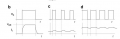
Here is the resultant voltages and current wave forms for a PWM signal for a fixed voltage supply.
Top voltage.
Bottom Current waveform.
Max.

upload_2019-2-1_14-15-3.png
 

ebeowulf17

Joined Aug 12, 2014
3,307
I'm with @BobTPH , @MisterBill2 , and others on this reducing current/increasing voltage question. Unless there's a lot of secret inductance or capacitance in the system that you're not telling us about, the instantaneous voltage and current will be essentially the same, regardless of duty cycle. As previously stated, the "average" current will only exist as an artifact of slow multi meter response time. There's never a moment when "average" current is flowing. It's either on or off.
 

Norfindel

Joined Mar 6, 2008
326
Well, that makes a lot of sense. The strips are resistive loads, and the PWM is just turning them 100% on and off very quickly, and so:

While the leds are on, the current is the same than in the case of the continuously-powered leds, and the same voltage drop is to be expected on the wire.

While the leds are off, there is no current and no voltage drop, so the voltage at the input of the PWM circuit will be the total voltage of the PSU, but as the leds are off, that will have no effect on the leds. It's unlikely that the slightly higher voltage will affect the PWM circuit, but if you have some specs, check them.​
 

Reloadron

Joined Jan 15, 2015
7,908
Thinking about this more and short of trying it on the kitchen table I really doubt it will matter, going against my earlier thinking or likely over thinking. I agree with Bill and sghioto. I would also look at things this way. You are building a light bar or several light bars or stands. These are for photography. You likely have a few grand between camera and lens easily. I would invest in some decent higher end AWG 14 for your wire. I have used some expensive AWG 12 with strands so fine you could tie small knots with the stuff. Do it right and eliminate the needs of compensating for any voltage drops.

Ron
 
Top