UP / Down Counter Using Rotary Encoder

Thread Starter

MCU88

Joined Mar 12, 2015
358
Hello...

I am working on this:


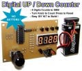
I want to save the current display number in EEPROM so that when power is removed and reapplied it will restore to this number. Pressing the rotary encoder to reset the count.

With everything that I have tried doing the display flickers when incrementing or decrementing the count using the rotary encoder because of the 5mS of time required to write to the EEPROM. So I have tried writing on-the-fly i.e each time the display number changes it gets written to memory.

Any suggestions? Much appreciated!

My code is here:
Code:
unsigned short i = 0;
unsigned short j = 0;
unsigned short scan = 0;
unsigned short rLeft = 0;
unsigned short rRight = 0;
unsigned short rotating = 0;
signed short ones = 0;
signed short tens = 0;
signed short hundreds = 0;
signed short thousands = 0;

// :: Defines :: //

// Displays ...
#define dslpD PORTA.F1
#define dslpC PORTA.F0
#define dslpB PORTA.F3
#define dslpA PORTA.F2

// Segments ...
#define segA PORTB.F7
#define segB PORTB.F5
#define segC PORTB.F3
#define segD PORTB.F2
#define segE PORTB.F1
#define segF PORTB.F6
#define segG PORTB.F4

#define rotary02 PORTB.F0
#define rotary01 PORTA.F4
#define rotary03 PORTB.F3

void num0()
{
  segA = 1;
  segB = 1;
  segC = 1;
  segD = 1;
  segE = 1;
  segF = 1;
}

void num1()
{
  segB = 1;
  segC = 1;
}

void num2()
{
  segA = 1;
  segB = 1;
  segG = 1;
  segD = 1;
  segE = 1;
}

void num3()
{
  segA = 1;
  segB = 1;
  segC = 1;
  segD = 1;
  segG = 1;
}

void num4()
{
  segF = 1;
  segG = 1;
  segB = 1;
  segC = 1;
}

void num5()
{
  segA = 1;
  segF = 1;
  segG = 1;
  segC = 1;
  segD = 1;
}

void num6()
{
  segA = 1;
  segC = 1;
  segD = 1;
  segE = 1;
  segF = 1;
  segG = 1;
}

void num7()
{
  segA = 1;
  segB = 1;
  segC = 1;
}

void num8()
{
  segA = 1;
  segB = 1;
  segC = 1;
  segD = 1;
  segE = 1;
  segF = 1;
  segG = 1;
}

void num9()
{
  segA = 1;
  segB = 1;
  segC = 1;
  segF = 1;
  segG = 1;
}

void blankDigit()
{
  segA = 0;
  segB = 0;
  segC = 0;
  segD = 0;
  segE = 0;
  segF = 0;
  segG = 0;
}

void displayOff()
{
   dslpA = 0;
   dslpB = 0;
   dslpC = 0;
   dslpD = 0;
}

void decCount()
{
   if (ones != 0 || tens != 0 || hundreds != 0 || thousands != 0)
   {
      ones--;

      if (ones < 0)
      {
         if (tens > 0)
         {
            ones = 9;
            tens --;
         }
         else if (hundreds > 0)
         {
            if (tens == 0)
            {
               tens = 9;
               ones = 9;
               hundreds --;
            }
         }
         else if (thousands > 0)
         {
            if (hundreds == 0)
            {
               if (tens == 0)
               {
                  tens = 9;
                  ones = 9;
                  hundreds = 9;
                  thousands --;
               }
            }
         }
      }
   }
}

void incCount()
{
   if (ones != 9 || tens != 9 || hundreds != 9 || thousands != 9)
   {
      ones++;

      if (ones > 9)
      {
         ones = 0;
         tens ++;
      }
      if (tens > 9)
      {
         tens = 0;
         hundreds ++;
      }
      if (hundreds > 9)
      {
         hundreds = 0;
         thousands ++;
      }
   }
}

void rstCount()
{
   ones = 0;
   tens = 0;
   hundreds = 0;
   thousands = 0;
}

void pollRotaryEncoder()
{
   TRISB = 0x09;
   
   if (rotary03 == 0)
   {
      rstCount();
   }

   TRISB = 0x01;

   if (rotary01 == 0)
   {
      if (rotary02 == 0)
      {
         rotating = 1;
      }
   }

   if (rotating == 1)
   {
      if (rotary01 == 1)
      {
         rRight = 1;
         rotating = 0;
      }
      if (rotary02 == 1)
      {
         rLeft = 1;
         rotating = 0;
      }
   }

   if (rotary01 == 1)
   {
      if (rotary02 == 1)
      {
         if (rleft == 1)
         {
            incCount();
            rLeft = 0;
         }
           
         if (rRight == 1)
         {
            decCount();
            rRight = 0;
         }
      }
   }
}

void setDigit(signed short digit)
{
   switch (digit)
   {
      case 0:
         num0();
         break;

      case 1:
         num1();
         break;

      case 2:
         num2();
         break;

      case 3:
         num3();
         break;

      case 4:
         num4();
         break;

      case 5:
         num5();
         break;

      case 6:
         num6();
         break;

      case 7:
         num7();
         break;

      case 8:
         num8();
         break;

      case 9:
         num9();
         break;
         
      case 10:
         blankDigit();
         break;

   }
}

void multiplexDisplays()
{
  displayOff();
  blankDigit();
         
   switch (scan)
   {
      case 0:
         setDigit(ones);
         dslpA = 1;
         break;

      case 1:
         setDigit(tens);
         dslpB = 1;
         break;

      case 2:
         setDigit(hundreds);
         dslpC = 1;
         break;

      case 3:
         setDigit(thousands);
         dslpD = 1;
         break;
   }

   scan++;

   if (scan == 4)
   {
      scan = 0;
   }
}

void main()
{
  CMCON = 7;            // Disable analog comparators
  TRISA = 0x10;         // PortA as output ...
  TRISB = 0x01;         // 4 inputs & 4 outputs
  PORTA = 0x00;         // Init port, all pins low
  PORTB = 0x00;         // Init port, all pins low

  Delay_ms(500);
  // :: Infinite program loop :: //

  while(1)
  {
     multiplexDisplays();
     Delay_us(100);
     pollRotaryEncoder();
  }
}
 

Attachments

ErnieM

Joined Apr 24, 2011
8,377
Probably the easiest thing to do is dump the display multiplex code into an ISR so it just runs all the time and the EEPROM delay does not interfere with the updates.

I do hope you've checked how many write cycles your EEPROM has. Seems to me like you will overtax the thing fairly quickly doing all those writes to it.
 

Thread Starter

MCU88

Joined Mar 12, 2015
358
Probably the easiest thing to do is dump the display multiplex code into an ISR so it just runs all the time and the EEPROM delay does not interfere with the updates.

I do hope you've checked how many write cycles your EEPROM has. Seems to me like you will overtax the thing fairly quickly doing all those writes to it.
What is an ISR? And can you elaborate on how to implement it?

What if I were to somehow detect when the circuit is powered down and then just do one write to the EEPROM, somehow but with no power, no that won't work...

Yes indeed that is the other problem as you say write cycle life of the EEPROM.
 

ErnieM

Joined Apr 24, 2011
8,377
ISR: Interrupt Service Routine. Try Google.

I have no idea how you could implement this as your device and compiler are still mysteries.

A power fail signal isn't rocket science. Basically all you need is a cap to supply 5mS (plus) of power to the device, a diode to isolate it from the rest of the unit, and an input pin to ping when power is lost. This ping pin needs be have an interrupt function as this event needs top priority handling.
 

Thread Starter

MCU88

Joined Mar 12, 2015
358
ISR: Interrupt Service Routine. Try Google.

I have no idea how you could implement this as your device and compiler are still mysteries.

A power fail signal isn't rocket science. Basically all you need is a cap to supply 5mS (plus) of power to the device, a diode to isolate it from the rest of the unit, and an input pin to ping when power is lost. This ping pin needs be have an interrupt function as this event needs top priority handling.
Yeah thanks for that. It makes sense what you say about the:

a. Cap to discharge power for 5mS EEPROM write
b. Diode to isolate 1n914
c. Pin to detect logic low

I am using the mikroC compiler and an PIC16F628 MCU.
 

jpanhalt

Joined Jan 18, 2008
11,087
What chip are you using?

The write time per byte of the 16F628A is 4 mS nominal, 8 mS max. The minimum write voltage is 4.5V. Without knowing the current the circuit draws, an exact calculation cannot be made. Assuming that is 25 mA, you will need a fairly large capacitor (roughly 500 to 1000 uF) to supply current after disconnecting the battery.

Why not use an on/off switch, like a push button? Then you can detect the switch closure and shut the system down in an orderly fashion while retaining the last value. Startup wouldbe the converse and also done in an orderly manner.

John

Edit: The 4 mS was from a Microchip forum. The datasheet gives 4 mS for block erase and 2 to 4 mS for a single write. It will still require a fairly large capacitor.
 
Last edited:

Thread Starter

MCU88

Joined Mar 12, 2015
358
Why not use an on/off switch, like a push button? Then you can detect the switch closure and shut the system down in an orderly fashion while retaining the last value. Startup wouldbe the converse and also done in an orderly manner.
Put the PIC in sleep mode when it is off? Yeah I guess this is another way of doing it. Many ways to skin a cat ;)
 

jpanhalt

Joined Jan 18, 2008
11,087
Sorry for the multiple edits. So, instead of making others suffer my misreading, here is the relevant timing table ( I misread the program flash values as EEPROM:

upload_2015-3-15_10-6-13.png

As for sleep when it is off, how will you turn it "off?" And yes, sleep would save current and retain your value.

John
 

Thread Starter

MCU88

Joined Mar 12, 2015
358
Be nice to find a way that does not involve me modifying the PCB for additional parts. I currently have an slide switch as the power switch for the circuit.

Keep your ideas coming. Thanx!
 

ErnieM

Joined Apr 24, 2011
8,377
This is why we complete the design before going to a PCB ;-)

OK so for a no parts change solution... If you are twiddling the knob things are changing so no need to keep each and every value, just need them to be saved when you are done changing things.

So reset a timer every time the know changes, then wait something "reasonable" (on the order of a few seconds) and if the know is not changes then store the new value.

May not catch every final value but should be close most of the time.
 

Thread Starter

MCU88

Joined Mar 12, 2015
358
This is why we complete the design before going to a PCB ;-)
I prototype straight to PCB now. I used to veroboard my projects first, but I can pop out an single sided board in my garage in under 30-minutes. I never get a project right the first time.

May not catch every final value but should be close most of the time.
May not catch every time? Well engineering is all about compromise. The user would still see the display flicker every time the timer function wrote to the EEPROM. So I guess this would be the compromise.
 

ErnieM

Joined Apr 24, 2011
8,377
Wish I could get out a board like that. My stuff can't fit on a single sided board so I rely on solderable protoboards and wire.

There's no reason the display should flicker when updating the EEPROM.

Loosing power while writing to the EEPROM is an inherent problem with this design no matter when you save the last value. Loss of power during the write leads to corrupted data.

BTW there is no need to hold up the display, just the PIC controller.
 

Thread Starter

MCU88

Joined Mar 12, 2015
358
Wish I could get out a board like that. My stuff can't fit on a single sided board so I rely on solderable protoboards and wire.
There's no reason the display should flicker when updating the EEPROM.
I like drawing boards. Kinda like an jigsaw puzzle, especially with single-sided boards that require multiple wire links.

Loosing power while writing to the EEPROM is an inherent problem with this design no matter when you save the last value. Loss of power during the write leads to corrupted data.
BTW there is no need to hold up the display, just the PIC controller.
Well that is another problem. I agree that the data would become corrupted if the MCU was in the middle of an EEPROM write and power was lost. I am leaning towards having a power fail schema with the capacitor, diode and detect pin transition from logic states high to low then write to EEPROM.
 

Thread Starter

MCU88

Joined Mar 12, 2015
358
Problem though is that the diode will conduct when the supply falls 0.6V below what the cap has charged to, and the pin to detect the power fail will have to see <27% of VDD (standard CMOS specs 27% for logic low) -- I cannot see how this will work now!
 

ErnieM

Joined Apr 24, 2011
8,377
OK, looks like there is no min spec for EEPROM write so equate that with the PIC operating range down to 2V, the PIC itself takes some 3mA running at 20M, and we need to keep things going so 10mS minimum... so that means a cap of: 3mA * 10mS / (5V-2V) or 10 uF. That's a min, I'd use lots more.

As long as you can separate the PIC power from everything else (do check sneaky paths) the power sense/holdup need not be more complicated than this:


Attachments

Thread Starter

MCU88

Joined Mar 12, 2015
358
OK, looks like there is no min spec for EEPROM write so equate that with the PIC operating range down to 2V, the PIC itself takes some 3mA running at 20M, and we need to keep things going so 10mS minimum... so that means a cap of: 3mA * 10mS / (5V-2V) or 10 uF. That's a min, I'd use lots more.

As long as you can separate the PIC power from everything else (do check sneaky paths) the power sense/holdup need not be more complicated than this:

I am not sure how to add this to the schematic. As in to just power the MCU and not the peripherals hanging off it.

Can someone add the schema to this schematic:


Attachments

ErnieM

Joined Apr 24, 2011
8,377
The diode and resistor go between the +5V line and pin 14 of the PIC. Pin 14 is the PIC PWR pin. The only spare pin you have is RA4.

RA4 has no direct interrupt ability by itself as some RB pins have. So you can either poll the pin (test it very often) to see if power was lost, or use the other function of RA4 to be a clock for timer 0. If timer 0 is loaded with a value of 255 the next clock will cause a roll over which can generate an interrupt. That's a bit of finicky code but should work.

OR... just put in your overall device spec "power must remain on for 1o seconds minimum after changing rotary knob to properly save setting. Failure to observe this limit may corrupt the stored value."
 

Thread Starter

MCU88

Joined Mar 12, 2015
358
OR... just put in your overall device spec "power must remain on for 1o seconds minimum after changing rotary knob to properly save setting. Failure to observe this limit may corrupt the stored value."
I could sleep at night with that. There are guys on the net selling electric superchargers for your car. What a load of rubbish! Complete rip off. eBay allow them to operate in business too !!!
 
Top