Unknown Inductor in Circuit

Thread Starter

dw85745

Joined Oct 5, 2015
32
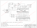
I'm just learning and am using an old digital clock for learning circuit analysis.
The digital clock shows power (LED panel lights almost all the various segments) but will not allow one to set or show the time.
Initially I found two resistors (replaced) which were bad but there is also an unknown inductor that appears open (no continuity).
I downloaded the datasheets for the onboard chip (both TI and Sanyo datasheets as well as someone else's circuit using this chip - all attached) but none show an inductor being used.
Question:
Since the inductor does NOT have a value (just plastic cover in yellow), how do I go about determining the inductors value?
(For example need to hand draw the circuit rather than relying on the datasheets, use some piece of equipment -- my multimeter has Hz)?
 

Attachments

Thread Starter

dw85745

Joined Oct 5, 2015
32
Can you give us a good photo of this inductor?
Sadly no. Don't own a digital camera or cell phone -- believe it or not.

Inductor looks similar to an electrolytic cap with the yellow plastic cover.
I cut the plastic cover and there is a coil of very thin wire wrapped many times around the center axis of a black spool (bobbin).
There appears to be "something" (kinda "looks like" a yellowish hot glue) leaking from the center of the spool
that has run down from the spool to the PCB.
 

DickCappels

Joined Aug 21, 2008
10,661
There is no continuity, therefore it would be very, very, very difficult to measure the inductance:).

Can you tell what part of the circuit the inductor is located? That might allow us to take a stab at a good value.

Also what is the part number for the clock IC?
 

Thread Starter

dw85745

Joined Oct 5, 2015
32
Thanks for responding.
There is no continuity, therefore it would be very, very, very difficult to measure the inductance
That is what I was concerned over.
One thought I had was to measure the wire thickness (current best guess without measure is 24 or 26 gauge) and length of wire (If I can get it intact off the spool.)
Don't know what the core is, but maybe with that info I have enough to get a best guess ??

what is the part number for the clock IC?
There is no separate Clock IC. From what I can determine -- based on my limited knowledge -- is the 60Hz from the transformer is used for the clock pulse. There is also a battery backup and a CR pin on the Primary IC. Following explains that:

https://forum.allaboutcircuits.com/...r-pin-on-an-ic-stand-for.152010/#post-1304252
 
Last edited:

MisterBill2

Joined Jan 23, 2018
27,513
Interesting problem indeed. Two things are available, the first is to trace out the circuit associated with the inductor. It may just be a filter, in which case almost anything the same physical size may be close enough. The other option, if you can get hold of a good magnifier, and a sharp needle, is to unwind the wire and find the break, which is probably at the inside end of the coil, and then rewind it after re-connecting the inside end of the wire. Also, the black material may well be ferrite or powdered iron, to provide more inductance in a small volume. However, if it is part of a switching regulated power supply then the exact value may be more critical. But repairing it should work.
 

ebp

Joined Feb 8, 2018
2,332
If the core of the inductor is hard and nearly black, it is probably a ferrite, which is a ceramic made mostly of iron oxide.

I suspect the inductor might be part of a noise filter for the 60 Hz clock for the IC. A little bit of circuit tracing could confirm that. Lack of the 60 Hz clock might be why the circuit doesn't respond to the buttons. Inductors are sometimes used in filters in power supplies, but since the LEDs light up with an open-circuit inductor that is very unlikely.
 

Thread Starter

dw85745

Joined Oct 5, 2015
32
Thanks for responding:and suggestions.

But repairing it should work.
That may be easiest option.

trace out the circuit associated with the inductor
Easier said than done, but if repairing doesn't work will give it a good effort.

black material may well be ferrite or powdered iron
and
If the core of the inductor is hard and nearly black, it is probably a ferrite
As stated in #3, material coming from center core looks more like hot glue (yellow and hard).
However, never considered the spool (bobbin) may be metal.
Will know for sure after disassembly.

I suspect the inductor might be part of a noise filter for the 60 Hz clock for the IC
That's my thought. I figure with the inductor broken, the 60Hz and DC battery backup can't get to IC. Also assumed voltage was getting to IC via anothe=r route hence LED at least lighting.
 
Last edited:

ScottWang

Joined Aug 23, 2012
7,501
Your replies hard to understand whom you reply to, please reverse the sentence who you like to reply and it will shown up as "+ Quote | Reply" and you can click the "Reply", so it will quote all the sentence with the ID and paste on the messages box.

Thanks for responding:and suggestions.
reply 1

That may be easiest option.
reply 2

Easier said than done, but if repairing doesn't work will give it a good effort.
reply 3
 

DickCappels

Joined Aug 21, 2008
10,661
I see the clock chip is an LM8560. I also see one place in that circuit I would put a small ferrite inductor, and that would be across the piezo speaker to increase the voltage to the speaker. It is a very common technique. If I were to guess the inductor is probably 33 mH or higher.

In this case the speaker would be driven through a transistor connected to ALARM OUT (pin 16 in the datasheet I am looking at) to increase current.

www.paulanders.com/G5-LED/ver1/datablad.pdf
https://www.alldatasheet.com/datasheet-pdf/pdf/41215/SANYO/LM8560.html

Remember this is only a guess.
 

Thread Starter

dw85745

Joined Oct 5, 2015
32
Mr. Cappels thanks for responding.

FWIW: This IC is stamped Texas Instruments. Post #1, attaches several datasheets and a circuit for this IC including TI.
---------------------------------
Re: inductor:
---------------------------------
1) Put a magnet to the spool of the inductor and it is"metal" per MisterBill2 and ebp.
2) There are No transistors on the board I am looking at. There is another board that mounts all the switches but will pull and verify.no transistors.
3) If the inductor is for the speaker then -- with my limited knowledge - it should have nothing to do with the clock circuit (??) and hence no impact.
on why the clock is not showing time.
4) Placement of the inductor on the PCB -- near rectifier diode(s) - would seem to me to indicate otherwise (but what do I know).

----------------------------------------------
Re: Datasheets -- Transformer and Ground
----------------------------------------------
1) The datasheets and schematics show a center tapped transformer. However this PCB does NOT use one. Only two wires coming off transformer.
2) "Assuming" where battery (-) lead connected to PCB is ground .

--------------------
Question
-----------------
1) Would it be best if I try and draw up this circuit, since different than those in Post #1 ??
-- or --
2) Take some voltages and post them?
 

DickCappels

Joined Aug 21, 2008
10,661
You might get more useful imsight by comparing the signals on the chip with what the datasheets indicate. In other words since you have a datasheet you can probably do some troubleshooting.
 
Top