Unexpected result with peak detector circuit. Design help needed

Thread Starter

SeanV123

Joined Nov 12, 2020
139
Hello,
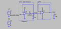
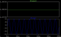
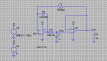
I am struggling with designing a peak detector circuit. I do not understand why I am unable to get the output to hold at Vpeak (5V). It is constantly holding at 4.5V. I cannot seem to understand why the opamp won't compensate for the diode voltage drop. The schematic, input and output traces and opamp parameters are shown below. Any design tips are appreciated. Thank you.1792680969226.png1792680986891.png1792681005774.png
 

dl324

Joined Mar 30, 2015
18,490
I'd remove D4 and R2. Open circuit D4 and short R2.

I'd also turn off that ugly grid, line up the grounds (or connect them together), connect V3 directly to the input of U1, change the label VCC to 9V, and even up the spacing of wires and components.
 

MisterBill2

Joined Jan 23, 2018
28,485
Certainly D4 is reversed from what is required. And the purpose of R2 is not clear.
AND that grid of dots serves no useful purpose, aside from making the image file much larger.
 

Thread Starter

SeanV123

Joined Nov 12, 2020
139
I have shared the .asc file in a comment
Certainly D4 is reversed from what is required. And the purpose of R2 is not clear.
AND that grid of dots serves no useful purpose, aside from making the image file much larger.
I have changed the design but the issue still persists! The updated file is in the replies
 

Thread Starter

SeanV123

Joined Nov 12, 2020
139
One thing to note. A low frequencies (1k-10kHz), the output is stable at 5V. It only drops to 4.5V when the input goes up to around 100kHz
 

crutschow

Joined Mar 14, 2008
38,909
Try C1 reduced to 10nF (why such a large capacitor) and D1 changed to a fast switching diode (e.g. 1N4148) from the slow 1N4007 rectifier diode:
At 100kHz you are running into the frequency response limitations of the op amp.

What is the maximum frequency you actually need?
 

Thread Starter

SeanV123

Joined Nov 12, 2020
139
Try C1 reduced to 10nF (why such a large capacitor) and D1 changed to a fast switching diode (e.g. 1N4148) from the slow 1N4007 rectifier diode:
At 100kHz you are running into the frequency response limitations of the op amp.

What is the maximum frequency you actually need?
I would like to have it fairly robust so let’s a max of 100k
 

crutschow

Joined Mar 14, 2008
38,909
What's the lowest frequency (i.e. what's the allowed droop rate on the held voltage) and how will will the peak voltage be reset for the next measurement?
 

crutschow

Joined Mar 14, 2008
38,909
Would it be okay to go with a 4V maximum peak input voltage instead of 5V?
4V makes it easier to get a low-cost, CMOS op amp (which operates on 5V power) that will meet your requirements.
 

Thread Starter

SeanV123

Joined Nov 12, 2020
139
Would it be okay to go with a 4V maximum peak input voltage instead of 5V?
4V makes it easier to get a low-cost, CMOS op amp (which operates on 5V power) that will meet your requirements.
There’s no specific design requirements or use case for this. I’m just designing this out of interest and to learn!
 
Top