And idle current of 38 ma in one and 34 ma in the other, I would think the filaments are ok.
A ~ 10% difference.
Most tube circuits have wide tolerances. It was just a drive by comment on the tube glow.........I haven't been keeping up on your project or mods.
The amplifier came with 2 6ca7's it had the difference in filament glow, so i had el34's laying around that i know work, i put those in, still weird glow issue
I would have though that if the problem was circuit related, the effect would stay with the socket and not move with the tube.
Anyhow, you may want to check or replace the two 270kΩ grid bias resistors.
I would have though that if the problem was circuit related, the effect would stay with the socket and not move with the tube.
Anyhow, you may want to check or replace the two 270kΩ grid bias resistors.
I don't know......I don't have a data sheet. I wouldn't suspect the filaments for the un-even current.
But you can verify the filaments by measuring the voltage across them and the current thru them. It's easy to check because of point to point wiring and alligator clips.
But before you do that, check for a grid bias difference. That's probably what's causing the different in plate current.
I don't know......I don't have a data sheet. I wouldn't suspect the filaments for the un-even current.
But you can verify the filaments by measuring the voltage across them and the current thru them. It's easy to check because of point to point wiring and alligator clips.
But before you do that, check for a grid bias difference. That's probably what's causing the different in plate current.
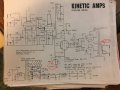
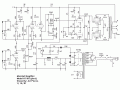
okay. Well. I fixed it. replacing the coupling caps somehow did it. Anyway. I now want to get onto shaping the tone. heres a schematic of the amplifier I am trying to mimic in tone. here is mine. The preamps look exactly identical and most of the power section except the ultralinear operation. The current amp just does not have the marshall "bite" to it and I think its because well the whole power section is different. What are some things to change to get closer to the tone I want
You have a High Fidelity tube amp vs a tube amp designed for a musical harmonic sound (Marshall). You might disconnect the ultralinear taps and re-bias the screen electrodes to change the grid/plate current curve of the output stage by eliminating the feedback effect on the beam optics. I'm not a musician so I would adjust the amp for the most accurate reproduction and adjust the input signal for the sound I want. http://www.dos4ever.com/uTracer3/Schade.pdf http://www.pmillett.com/file_downloads/ultralinear.pdf http://www.tpub.com/neets/book6/21a.htm
You have a High Fidelity tube amp vs a tube amp designed for a musical harmonic sound (Marshall). You might disconnect the ultralinear tap and rebias the screen electrodes to change the grid/plate current curve of the output stage by eliminating the feedback effect on the beam optics. I'm not a musician so I would adjust the amp for the most accurate reproduction and adjust the input signal for the sound I want. http://www.dos4ever.com/uTracer3/Schade.pdf http://www.pmillett.com/file_downloads/ultralinear.pdf http://www.tpub.com/neets/book6/21a.htm
So basically disconnect the ultralinear taps and use a resistor to get the screen grid current wh within limits. Run a wire off of point A to the screen grid on the tube with a resistor to get proper screen current I mean. Here's whats on the data sheet:
Rg2: 470
Ig2: 2x11.5 - 2X22.5 Whats with the weird multiplication? Why not just 23 to 45?
Vg2 max: 800
How would I know what resistor value I am going to need? And once done how can I calculate screen current? (My usual method being Vdrop x transformer resistance. My current screen current is 36Ma.

 Facebook
 Google
 GitHub
 Linkedin