 Facebook
 Google
 GitHub
 Linkedin
Hi everyone,
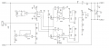
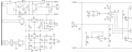
I am a student learning about variable power supplies. I am learning about linear and switching power supplies. I found a schematic online on a variable power supply but didn't understand the full circuit layout.
Complete_schematic_1_2, and Complete_Schematic_2_2 attached is the schematic of the variable DC power supply.
PS_Image_Q1/Q2/Q3/Q4 attached have boxes and/or arrows with a description of what I am confused about.

The main questions are:
1) Why are there 2 ground symbols in the schematic. I understand the concept between earth ground and common. They use an analog ground signal between two series capacitors at the output, however this analog ground is not used anywhere else in the circuit.
2) I don't understand how the return current from the output is measured with the IC1A op amp; how can you measure the return current if the return is not tied to the ground such as R57(0.1 ohm) resistor is.
3) What is the purpose of the op-amp IC3B? Does this limit the output current? If so, how? It is a voltage follower, the output of the op amp follows the reference voltage on the non-inverting pin, however how does this limit the output current?
4) According the the connector CON2, the signal OUT is connected to ground. This doesn't make sense(please see PS_Image_Q2 ).
I appreciate all the help!")
I am a student learning about variable power supplies. I am learning about linear and switching power supplies. I found a schematic online on a variable power supply but didn't understand the full circuit layout.
Complete_schematic_1_2, and Complete_Schematic_2_2 attached is the schematic of the variable DC power supply.
PS_Image_Q1/Q2/Q3/Q4 attached have boxes and/or arrows with a description of what I am confused about.
The main questions are:
1) Why are there 2 ground symbols in the schematic. I understand the concept between earth ground and common. They use an analog ground signal between two series capacitors at the output, however this analog ground is not used anywhere else in the circuit.
2) I don't understand how the return current from the output is measured with the IC1A op amp; how can you measure the return current if the return is not tied to the ground such as R57(0.1 ohm) resistor is.
3) What is the purpose of the op-amp IC3B? Does this limit the output current? If so, how? It is a voltage follower, the output of the op amp follows the reference voltage on the non-inverting pin, however how does this limit the output current?
4) According the the connector CON2, the signal OUT is connected to ground. This doesn't make sense(please see PS_Image_Q2 ).
I appreciate all the help!
Attachments
-
 107.9 KB Views: 48
 -
 132.4 KB Views: 48
 -
 108.8 KB Views: 39
 -
 95.5 KB Views: 37
 -
 111.4 KB Views: 36
 -
 88.6 KB Views: 30


