 Facebook
 Google
 GitHub
 Linkedin
Hi,
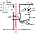
Let's consider the image attached. Also, an scenario where I have multiple power supplies. Should I connect all grounds to a common point?
I remember once that I had a circuit like the one attached, and didn't have the two grounds joined, so the circuit didn't work properly until I got the two grounds together (cathode ground and motor power supply ground), but why?
Attachments
-
 29.7 KB Views: 36

 "as well as the AC neutral" ? Are you sure that's how PC power supplies are wired?


