Understanding DC-AC inverter for pure Sine PWM

Thread Starter

Vindhyachal Takniki

Joined Nov 3, 2014
598
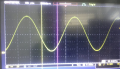
1. Need to design solar inverter dc to ac using pure sine wave PWM. I am reading a bit and this is what understand. I am using MCU with FPU enabled.
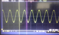
2. Have to change output freq from 1-400Hz(depending on user input) & output ac voltage from 110Vac-300Vac(depending on user input)


3. Currently i am understanding how to change freq:
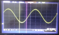
a) Whatever I have read on internet is using swtiching freq 20Khz or higher for pure sine wave since its outside audible range. So i am using 20Khz here. I dont know if its ok or higher need to be selected, what is criteria for it?
Since I am using IGBT of 10Amps for application, so cannot go above 20Khz, as they have limitation of their own.
With 20Khz , PWM time period = 1/20Khz = 50us.

b) Then I read to divide sine wave into equal parts some on intenet used 100, some 200 some 10. What is criteria for it?
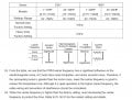
I am chosen 100 parts since it will divide 360 degree into 3.6 degree each.So an array of 100 values is made
arr[n] = Sin(n*Pi/180) where n varies from 0 to 99

Is it ok?
Then PWM will start with width variation and after every degree time period, corresponding PWM On time be selected, whereas PWM timer period is fixed at 50Hz so that switching freq is 20Khz always.
 

dendad

Joined Feb 20, 2016
4,636
When you say that you "need to design" this, what experience do you have that enables you to design the circuit?
Is this a home project or for a company?
This in not a trivial project.
 

Thread Starter

Vindhyachal Takniki

Joined Nov 3, 2014
598
Thanks for responses.
I have one doubt whether to go with fixed PWM period or fixed steps/360 degree.

I was reading this: http://www.ocfreaks.com/sine-wave-generator-using-pwm-lpc2148-microcontroller-tutorial/
Here it is mentioned : "For each division we have a single PWM cycle." So for number of steps we divide full cycle we will have fixed PWM period.

1. Suppose for ease of understanding using 50-400Hz variable.

2. I have uploaded excel file with two options: https://drive.google.com/open?id=1a_WLaLzs7RiUBYA6N0_hSOvFjJV2TrD3

Also attached pdf of same excel also
a) fixed steps 360 & keep swtiching freq variable (i.e 1 step per degree)
b) fixed switching freq(20Khz) & keep steps variable (20Khz as this is max freq for most igbt)
I prefer 4 igbt in H bridge configuration.


A) Fixed steps & keep PWM period(swtiching freq) variable:
1. At 50hz, time period = 1/50hz = 20ms
2. If keep 360 steps fixed, then time_per_step = 20ms/360 = 55.55us/step
3. 55.55us means swtiching freq will be 18khz around.
4. But if intial freq is 400Hz, then switching freq by this calculaltions will be 144Khz, which is very high .


B) Fixed switching freq i.,e 20Khz i.w PWM period = 50us & keep steps variable
1. At 50Hz, steps will be = 20Khz/50Hz i.e 400 steps
2. Time period per step = (1/50)*1000000/400 = 50us
3. So for 50hz, need to divide into 400 steps. For 400 steps, each step sine value is calculated as in excel.
4. Now for each step, 50us PWM period is fixed, so on_time varies. As in excel it changes from 0.78us to 50us(o tp 90 degree) & cycle continues.

I am not sure if igbt can work with such low on_times?
Normally igbt have max switching freq of 20Khz mentioned, so I assume this means 25us on time and 25us off time max?

Are my calculations correct.

I have been able to generate sine wave by measuring directly at PWM output of MCU & connecting low pass filter of cut off 800hz around. Level shifted for negative cycle.

I am not sure which way is correct? Can anyone tell?
Is my understanding correct or other way to do it?
 

Attachments

Thread Starter

Vindhyachal Takniki

Joined Nov 3, 2014
598
By keeping fixed PWM freq 20Khz, i.e 50us time period, and variable steps to divide the sine wave i been able to generate it across MCU pin and connecting simple low pass filter, been able to generate sine wave acroos it for 50,100 & 400Hz, as in pic attached.

For example:
1. For 50hz, divide 360 degree into 20Khz/50hz = 400 steps
2. For 100hz, divide 360 degree into 20Khz/100hz = 200 steps
3. For 400hz, divide 360 degree into 20Khz/400hz = 50 steps
All caculations will be caried with FPU enabled MCU only, cortex M4.

I was reading some article on delta for carieer freq. They have default 4Khz and can go to max 15Khz.


Now I have some doubts:
1. Currenlty i am able to generate sine wave as desired but on MCU only. is it correct way to do that?

2. If it is, then next step is to select igbt of 20Khz switching freq. But have doubt that on_time varies from 0 to 50us? Can igbt work when on_time is near zero?
For example for 50Hz, PWM period is fixed 50us(20Khz), on time varies from 0 minimum, then next minimum is 0.78566us. SO can igbt turn on at this low time? Datsheet specify only 20Khz switching freq max. But i dint find minimum allowable on_time/off_time?

3. For initial for safety, will start with low voltages like 24Vdc and gradually increases to 220Vmax.
 

Attachments

Thread Starter

Vindhyachal Takniki

Joined Nov 3, 2014
598
Need to drive a 3 phase induction motor.

Delta vfd page attached, default carrier is 4Khz only. But why is that so? Wont it create audible noise more?


With current setup with MCU I am able to genearte sine PWm from 50-400Hz without issue.

But now i need to vary amplitude also of output from 110Vac-300Vac? How to do that? Will that by same formula for sine wae?
y= Asin(angle) ?? current setup I have taken A=1in formula.

Will varying A will vary amplitude also? I have tried it , it seems to work. But I am not sure if that is ok or not or this is how its done in vfd's??
 

shortbus

Joined Sep 30, 2009
10,050
But now i need to vary amplitude also of output from 110Vac-300Vac? How to do that? Will that by same formula for sine wae?
That is something none of the VFD's I own and use can do. They are called Variable Frequency Drives, not Variable Voltage Drives. Where would the extra voltage come from? That requires a transformer and when you step up voltage with a transformer you loose amperage.
 
110Vac-300Vac

Unfortunately, you don;t have RPM and field strength to vary frequency and amplitude.

I've seen and worked on one high power amplifiers use 2 positive and 2 negative rails.

if you needed 100, 120, 220, 240 and 277 you can work with transformer taps and "possibly" a way of linearizing the output.

You have the choice of "H-bridge" and the center-tap transformer method.

I have a 500W AC line voltage regulator made by Sorenson that I use for my audio amplifier.
 
Last edited:
Top