Understanding Avalanche Oscillator Circuit.

Thread Starter

Breakfastking

Joined Feb 26, 2020
2
Good day all,

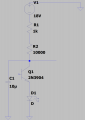
I did an experiment with the lookmumnocomputer avalanche oscillator as illustrated below.

I would like to understand the relationship between the potentiometer resistance and time constant/period value.

I tried patching the circuit on the breadboard and replace the circuit with a Light Dependent resistor.

A sawtooth output was obtained with a light resistance value of 2.5kOhms and a frequency of 7 Hz. However, despite that i am still unable to understand the relationship and operating principle.

Please assist.

1582704607405.png
Thanks

Faris
 

Attachments

sparky 1

Joined Nov 3, 2018
756
You might compare this oscillator circuit to one operating in a different region.
For example a sine wave oscillator might require a careful selection of resistor values to allow it to operate with very low distortion. A very finite adjustment and choice of component selection show the ability to follow a method to derive those parts of the circuit. The sine wave circuit having a different type of mode giving a different behavior. Acquiring method and skill level allows one to characterize the various oscillators and have fun building them to produce a predictable shape and time period.
 

kubeek

Joined Sep 20, 2005
5,794
I am not sure if ltspice is able to simualte this properly, but you sure do have the transistor connected backwards, emitter needs to be on the upper side. Basically the R-C combination along with the voltage on the power supply dictate how long it takes for the voltage on the cap to reach the avalanche voltage of the transistor, which here is about 12V. Then the transistor suddenly conducts and lets current from C into the LED.
 

Audioguru again

Joined Oct 21, 2019
6,673
In the grey simulation, both the transistor and the battery are backwards which is correct.
But then both the capacitor and the LED are connected upside down.

The maximum allowed reverse biased emitter-base of the 2N3904 transistor is 6V. The transistor must be connected backwards for the emitter-base to be reverse-biased and then it is in series with the collector-base diode and has avalanche breakdown when the capacitor voltage charges to 6V plus the 0.7V of the collector-base diode plus the LED voltage.

When the emitter-base has avalanche breakdown it conducts the capacitor charge into the LED, since there is no resistor to limit the LED current then the LED might burn out.
 

Tonyr1084

Joined Sep 24, 2015
7,853
Not sure if I understand the question you need answered, so I'll try a basic explanation of the circuit: C1 charges through R1. When the voltage reaches the avalanche voltage of the 2N3904 it conducts. Current flows from the cap into and through the LED. As the voltage of C1 drops off the transistor stops conducting and C1 begins charging again.

Changing the values of the cap and the resistor will change the frequency the LED flashes at.
 

Bordodynov

Joined May 20, 2015
3,177
The parameters of the transistors have variations. Some operate in the relaxation mode with increased current, others with reduced current. I have the letter L for low current transistors.
 
Top