 Facebook
 Google
 GitHub
 Linkedin
hey all need your biggg help here:
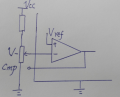
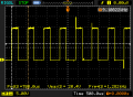
phenomenon: to realize an adjustable module PWM: UC3842 using switching power IC,open loop system; Vf pin was connected with Potentiometer adjustment feedback voltage, compensation pin was not connected. the result was not as i expected. i can indeed change the duty cycle via potentiometer outside, but in a very small arrange and not accurate enough, take D=60%, and a small move, it would turn to D=40% or 30% for example.
my speculation: if the compensation pin was disconnected, which means the op-amp is working in open cycle and linear range is very small and has a really big slope. then i should insert a resistor between voltage feedback pin and compensation pin to let the op-amp run in closed loop. is that okay?
if you have any theory and method, please give a hand here. thanks.
and there is one more thing: there are two frequencies named CH1 and freq1 on the oscilloscope, but i noticed occasionally that there's another frequency shown on the top-right place, what does that mean?
thanks again.
Attachments
-
 136 KB Views: 29
 -
 7.8 KB Views: 23


