Facebook
 Google
 GitHub
 Linkedin

Background
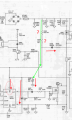
I'm repairing a monitor with a SMPS utilizing a UC3842 IC. I've tested the monitor in my shop and worked fine. When I get to the customer's site, it wouldn't startup. The difference is the input AC (My shop = 120 to 130 VAC. He's shop is 118VAC).
At his site, I tested the Vcc voltage to pin 7 of the UC3842. As soon as I touched pin 7, the monitor started right up, which made me believe that the conditioned triggered the UVLO to go at or above 16 VDC threshold to startup. I think this issue has something to do with a component in partial failure pulling down the voltage enough to stay around 15.25 VDC and not trigger the UC3842 to start
I've tested the startup resistors (2 x 82K Ohm), capacitors, and the MOSFET, but am stuck and not sure what else could possibly causing the issue. Any suggestions, or test techniques I'm not thinking about, would be greatly appreciated.
View attachment Neotec NT-500DX - SMPS Issue - UVLO.png
I'm repairing a monitor with a SMPS utilizing a UC3842 IC. I've tested the monitor in my shop and worked fine. When I get to the customer's site, it wouldn't startup. The difference is the input AC (My shop = 120 to 130 VAC. He's shop is 118VAC).
At his site, I tested the Vcc voltage to pin 7 of the UC3842. As soon as I touched pin 7, the monitor started right up, which made me believe that the conditioned triggered the UVLO to go at or above 16 VDC threshold to startup. I think this issue has something to do with a component in partial failure pulling down the voltage enough to stay around 15.25 VDC and not trigger the UC3842 to start
I've tested the startup resistors (2 x 82K Ohm), capacitors, and the MOSFET, but am stuck and not sure what else could possibly causing the issue. Any suggestions, or test techniques I'm not thinking about, would be greatly appreciated.
View attachment Neotec NT-500DX - SMPS Issue - UVLO.png
Attachments
-
3 MB Views: 10