Help in repairing UC3842 Circuit

Thread Starter

hazim

Joined Jan 3, 2008
435
Dear,
I'm a very old member, and just came back now to ask for your help.
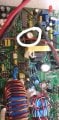
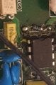
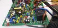
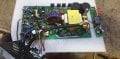
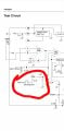
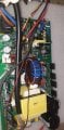
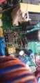
I have an electronic 48V 30A battery charger. This charger had problem with UC3842 2 times and we repaced it each time and got the charger working again.

This time we replaced it and can't find any other bad component, but the charger is not working. The supply voltage on the IC (between pin 7 and 5) is varying from approx 11.5VDC to 13VDC. I measured about 2V AC on there, which seems DC voltage is not filtered well, so I changef the electrolytic capacitors and still have the same problem.

I'm an electronics engineer and can undertand your help easily in order to fix it.

Regards,
Hazim
 

Attachments

AlbertHall

Joined Jun 4, 2014
12,338
Below is the typical circuit from the datasheet. I have drawn a red box around the components I would check first. Remember your circuit may be the same as this but it is likely to be similar.
Clipboard01.jpg
 

AlbertHall

Joined Jun 4, 2014
12,338
OK. Now it gets trickier! Something is preventing the supply running, or shutting it down immediately it starts.
Shorted output rectifier or capacitor.
Open MOSFET.
Open or shorted component in the gate drive.
 

Dodgydave

Joined Jun 22, 2012
11,277
What's the resistance of the start up resistor, what is the HV supply voltage. Check for shorted diodes on the output and the primary of the transformer.
 

Thread Starter

hazim

Joined Jan 3, 2008
435
Ok I found it, it was a shorted capacitor, it tested about 70 ohm, that was because the technician who tried to repair it before me melted the capacitor by mistake and made a short as shown in the picture.

Now the charger worked as it should and there is output voltage at the other side, about 59V, but the protection LEDs are on and the charger is not charging the batteries, on the display it gave 59V and 0A.
 

Attachments

Thread Starter

hazim

Joined Jan 3, 2008
435
Your charger is rated at 48V and the PSU is giving out 59V, maybe it's too high.
It used to be high like that when the batteries become full.
For a 12V battery it will charge till 14.8V then 4x12.8V = 59.2V.

But as it's 59V at open circuit, and also 59V when connected to the batteries but at 0A~0.27A, so there should be something in the protection circuit assuming the batteries to be full and stopping the charging current from flowing. That's what I think now.

What do you think? And what do you suggest to fix this problem?
 

Thread Starter

hazim

Joined Jan 3, 2008
435
We need better pictures of the charger PCB to assist you further..
Ok, that small transformer has the high voltage mosfet and uc3842 at one side, where we had the first problem and I fixed it. Now, on the other side I got output voltgage of 12-13V, and the screen on the inverter turned on and gives 54V~59V and 0A.

The relay at the corner, that black cube, has the charging voltage on one terminal but the protection circuit is making it off and not letting the current to flow to the batteries.

The problem now is why the protection circuit is activated and stopping the charger from working? Ofcourse I can disable this protection in some way or connect directly without the relay..etc but I should not do this and find what is causing the protection circuit to turn on.

Your help is strongly appreciated!

Best regards,
Hazim
 

Attachments

Thread Starter

hazim

Joined Jan 3, 2008
435
One important note, the IC used in the protection circuit is LM324N, it's output pin 14 is connected through resistor to shutdown pin 10 in IC KA3525 and voltage there is 0V. The shutdown is activated at 0V. So the problem should be around LM324 which I'm testing right now.

Update: I connected that resistor (4.7k) to Vref (5V) and kept the other terminal connected the shutdown pin, so the voltage at shutdown pin raised from 0V to about 2.3V which it should according to the datasheet (see attachment), but the protection cutoff problem still there.
 

Attachments

Last edited:

Dodgydave

Joined Jun 22, 2012
11,277
The KA3525 has a Dead Time on pin4, this pin should be at Zero for it to run Normally, if it goes above 1V then it will shut down.
 

Thread Starter

hazim

Joined Jan 3, 2008
435
The KA3525 has a Dead Time on pin4, this pin should be at Zero for it to run Normally, if it goes above 1V then it will shut down.
If it is above 1V, the problem will be in the circuit around the IC, where the voltage is comming, and not with the IC itself, right?
 
Top