µC based power source control for ebike

Thread Starter

simmck

Joined Aug 8, 2019
5
Hi everyone,
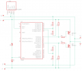
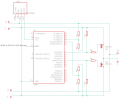
I am relatively new to electronics, but I have to build a µC based circuit, which will select the power source (one of two 36V Li-Ion batteries) for the ebike controller. I have come up with the circuit below, but I am not sure if this will work. I know that these batteries are dangerous, so I will probably implement ideal diodes on the high sides. What I am not sure about is, if the n-channel mosfets (Nexperia Buk962r5-60e) will operate with the the shared GND between the batteries. I haven't determined all of the values yet, as I need to know, if I am on the right path.

There should only be one batterie attached at all times !

Details:
3.3 Buck Converter
Nexperia Buk962r5-60e LL n-channel
Teensy 3.2

Thanks guys !
 

Attachments

LesJones

Joined Jan 8, 2017
4,174
You have the two batteries connected directly in parallel so whichever mosfet is conducting you are still connecting the motor to both batteries.

Les.
 

Dodgydave

Joined Jun 22, 2012
11,284
Yes your batteries are connected together in parallel, you need to connect one battery Negative to one fet Source , and the Drain to the load, then that will power the load.. (do it for both batteries one for each fet) and leave all Positives connected together.
 

LesJones

Joined Jan 8, 2017
4,174
You are correct the diodes will mess up the ADC measurements. If I had been doing this I would have used P channel mosfets (Or relays) in the positive feeds. One solution I can think of is to have a positive reference voltage and have potential dividers between each battery negative and the the reference voltage. The output of each potential divider would go to an ADC channel. From that you could calculate the voltage drop across the diodes to add to the ADC readings from each battery positive reading. Note you can not measure the voltage drop across the diodes directly as this would be a negative voltage with respect to the logic ground.

Les.
 

Thread Starter

simmck

Joined Aug 8, 2019
5
Because of higher Rds I would like to switch with n-channel on low side. I build in the ideal diodes, with a LTC4357 an some unspecified n-channel mosfet. What are your thoughts on this solution ?

Thanks
 

Attachments

LesJones

Joined Jan 8, 2017
4,174
Q1 and Q2 will not serve any purpose. Why not use the same N channel mosfets to switch the positive rail using the same method used by the LTC4357 ? (Using a charge pump to generate a voltage about 10 volts more positive than the battery positive. ) If your schematic in post #7 had worked as I think you intended it to work then you would have had two N channel mosfets in series with the load.

Les.
 

Thread Starter

simmck

Joined Aug 8, 2019
5
So I have done some more research and reconsidered my design. To simplify the circuit I have chosen a high side PMOS set up. This way I can have a shared ground, which makes voltage measurement and switching easier.

Setup:
Q1&2 SQP90P06 | Vgs +-20V | Rdson 0.0067 Ohms | Id -120 A
R5&9 3.3k
R6&10 10k
NPN BC817K
Other Values not yet determed

When the PMOS are fully turned on at at least Vgs = -7,5V this would give me a Rdson of 0.0088 -> 15² * 0.0088 = 1.8 W
A TO220 with attached heatsink should be able to run this , no ?

P.S. Thanks so much for your patience and help. I'm a total noob regarding this, but as I learn more about this field, I get more excited. So much possibilities for creating amazing stuff. So thanks for helping out

Edit: Two seconds after posting, I realized that the body diodes of the PMOS will still allow currrent to flow in one direction. Any recommendations on this ?
 

Attachments

Top